
mosfet tester

The described circuit is an astable multivibrator configuration tailored specifically for testing N-channel MOSFETs, particularly power MOSFETs like the IRF830. The astable multivibrator is a type of oscillator that generates a continuous square wave output without requiring any external triggering. This circuit operates by alternately charging and discharging capacitors, which in turn controls the gate of the MOSFET being tested.
In this configuration, two resistors (R1 and R2) and a timing capacitor (C1) are connected to the MOSFET gate. The choice of resistor and capacitor values determines the frequency of oscillation, allowing for a range of test conditions. The output from the multivibrator can be connected to the gate of the MOSFET, enabling it to switch on and off rapidly. This rapid switching simulates the conditions under which the MOSFET would typically operate in a circuit.
To ensure accurate testing, the circuit may include additional components such as diodes for flyback protection, especially if inductive loads are involved. A power supply is required to provide the necessary voltage for the circuit, and it is crucial to ensure that the supply voltage is within the safe operating limits of the MOSFET being tested.
The output waveform can be monitored using an oscilloscope to verify the switching characteristics of the MOSFET. This includes observing the turn-on and turn-off times, as well as the gate threshold voltage. By adjusting the resistors and capacitors, the user can tailor the test conditions to assess the performance of different MOSFETs under varying frequencies and duty cycles.
Overall, this astable multivibrator-based testing circuit is a practical and efficient tool for evaluating the operational characteristics of power MOSFETs, providing valuable insights into their performance in real-world applications.This is a variation on the astable multivibrator. Circuit was recently developed to test for N-mosfets(the power kind e.g irf830).. 🔗 External reference
Related Circuits
This circuit includes a 220µF capacitor and two diodes designed to slow down the switch-on process, thereby minimizing the output thump that occurs as the output capacitor charges through the speaker. While this feature is not essential and may...
The tester provides an audible indication of the logic level of the signal presented to its input. A logic high is indicated by a high tone, a logic low is indicated by a low tone, and oscillation is indicated...
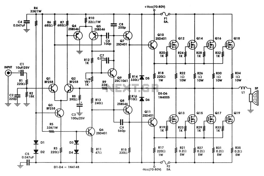
400 W MOSFET Audio Amplifier circuit using IRFP448. This circuit is categorized under amplifiers and includes five circuit diagrams. For more detailed information, refer to the main post titled "400 W MOSFET Audio Amplifier Using IRFP448." This post also...

The circuit diagram represents a useful tool for quickly testing various types of thyristors, including silicon-controlled rectifiers (SCRs) and triacs. For triacs, all four quadrants are assessed using switch S3, while testing a standard thyristor requires the adjustment of...
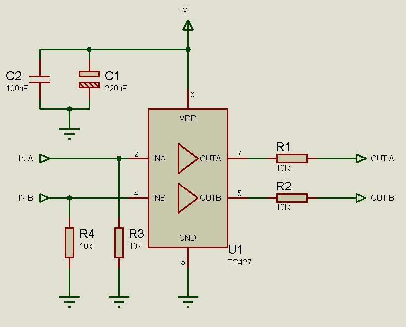
MOSFETs cannot simply be connected to the drive signal and expected to function correctly. Due to their construction, driving MOSFETs can be complex, particularly for beginners. Many users frequently seek assistance with MOSFET drive issues on various blogs, websites,...
Construct a compact battery-powered device that incorporates a servo motor. The design should include a mechanism to turn off the servo to conserve battery life. It has been noted that MOSFETs can be utilized for this purpose; however, there...