
MOSFET Toggle Switching circuit

When a switch is closed, the 1uF cap voltage is connected to the junction of the 220 ohm and 33K resistors causing the circuit to change state. When the switch is opened, the cap charges or discharges to the new level through the 1M resistor, and the circuit is ready to toggle again in about 1 second. It takes a little time for the cap to move to the new level, either +V or ground.
The (0.1uF) capacitor at the transistor base was added to suppress noise that might cause false triggering if the switches are located far away from the circuit. The circuit was tested using a 12 volt, 25 watt automotive lamp, and IRFZ44. Other MOSFETs can probably be used.
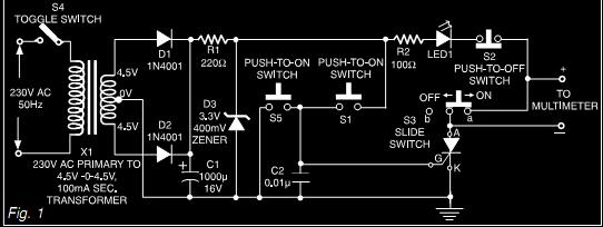
The described circuit functions as a toggle switch mechanism using momentary push buttons or normally open (N/O) switches to control a load from multiple locations. The design is reliant on a debouncing method to ensure stable operation, eliminating the potential for false triggering that can occur from mechanical switch bounce. The inclusion of the 10K resistor, 10µF capacitor, and a diode on the left side of the schematic plays a critical role in establishing the initial state of the circuit upon power-up. This configuration ensures that the load is off and the NPN transistor is in a conducting state, allowing for a predictable startup behavior.
Upon activation of any switch, the voltage across the 1µF capacitor influences the junction of the 220-ohm and 33K resistors, effectively toggling the state of the output. The design also incorporates a 1M resistor that allows the capacitor to charge or discharge, setting the timing for how quickly the circuit can be toggled again. This timing is approximately one second, providing a buffer to prevent rapid switching that could lead to erratic behavior.
The addition of a 0.1µF capacitor at the base of the NPN transistor serves as a noise suppression element, which is particularly beneficial in scenarios where the switches are located at a distance from the circuit. This helps to stabilize the control signal and prevent unintended toggling due to electromagnetic interference or other noise sources.
The circuit has been successfully tested with a 12-volt automotive lamp rated at 25 watts, utilizing an IRFZ44 MOSFET for load switching. The flexibility of the design allows for the substitution of other MOSFETs, provided they meet the necessary specifications for the application. Overall, this circuit provides a robust solution for remote load control with reliable toggling capabilities.This circuit was adapted from the "Toggle Switch Debounced Pushbutton" by John Lundgren. It is useful where the load needs to be switched on from one location and switched off from another. Any number of momentary (N/O) switches or push buttons can be connected in parallel. The combination (10K, 10uF and diode) on the left side of the schematic insures the circuit powers up with the load turned off and the NPN transistor conducting. These components can be omitted if the initial power-on condition is not an issue. When a switch is closed, the 1uF cap voltage is connected to the junction of the 220 ohm and 33K resistors causing the circuit to change state. When the switch is opened, the cap charges or discharges to the new level through the 1M resistor, and the circuit is ready to toggle again in about 1 second.
It takes a little time for the cap to move to the new level, either +V or ground. The (0.1uF) capacitor at the transistor base was added to supress noise that might cause false triggering if the switches are located far away from the circuit. The circuit was tested using a 12 volt, 25 watt automotive lamp, and IRFZ44. Other MOSFETs can probably be used. 🔗 External reference
Related Circuits
The circuit depicted can be utilized to control a unipolar stepper motor equipped with four coils. This design is derived from an older fax machine. The circuit is capable of handling a motor current of approximately 500 mA per...
If expecting an important visitor but needing to step out for a moment, an electronic doorbell memory can be useful to check if someone rang while away. Although it may not indicate whether the expected visitor arrived, a quick...
This circuit provides an initial voltage of 2.5V per cell to quickly charge a car battery. The charging current decreases as the battery charges, and when the current drops to 180 mA, the charging circuit reduces the output voltage...
Sometimes when experimenting with different soundcards and MIDI interfaces it is useful to see if there is some data going in MIDI interface. This can be easily tested with this adapter, which converts the midi signals to visible light...
This document describes a simple triac tester circuit that can also be utilized for testing silicon-controlled rectifiers (SCRs) and both PNP and NPN transistors. The circuit operates on 3V DC, which can be derived from a Zener diode combined...
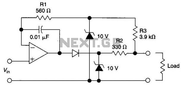
The circuit is designed to drive an external load. A fault condition in the external load circuit could feed excessive current or voltage back into the line drive circuit. If excessive voltage appears from the load, the two zener...