
stepper motor controller circuit
The circuit operates by energizing the coils of the unipolar stepper motor in a specific sequence, which facilitates precise control over the motor's rotation. The use of the SL100 transistor allows for efficient switching of the motor coils. When the motor is activated, current flows through the selected coil, generating a magnetic field that interacts with the rotor, causing it to turn.
In scenarios where higher current capacity is necessary, the 2N3055 transistor serves as a robust alternative. When configured as a Darlington pair with the SL100, it enhances the current gain, enabling the control of larger stepper motors without compromising performance. This configuration is particularly beneficial in applications that require rapid acceleration or deceleration of the motor.
The inclusion of diodes in the circuit is critical for protecting the transistors from voltage spikes that can occur when the inductive coils are de-energized. These transients can damage the transistors if not properly managed. The diodes function as flyback diodes, allowing the current generated by the collapsing magnetic field to dissipate safely, thus prolonging the lifespan of the components.
Overall, this circuit design is effective for controlling unipolar stepper motors in various applications, providing a reliable solution for precise motion control while ensuring the protection of sensitive electronic components.The circuit shown above can be used to control a unipolar stepper motor which has FOUR coils (I`ve swiped it off an old fax machine). The above circuit can be for a motor current of up to about 500mA per winding with suitable heat sinks for the SL100.
For higher currents power transistors like 2N3055 can be used as darlington pair along with SL100 . The diodes are used to protect the transistor from transients. 🔗 External reference
Related Circuits
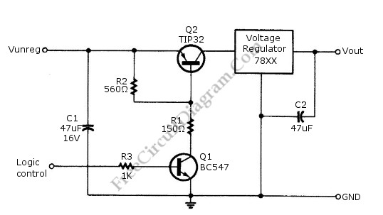
Logic power control of an analog regulator can be useful in applications where a digital circuit or controller needs to manage a power source, such as in EEPROM programmers or other power control systems. This circuit provides ON-OFF control...
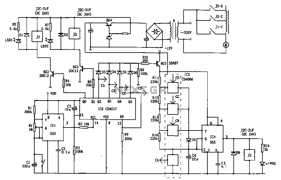
The AC welder operates intermittently, with power consumption during these periods reaching several hundred watts. The AC welder saving controller circuit enables the welding machine to automatically cut off power during no-load conditions while also automatically restoring power for...
The circuit diagram is designed for precise control of DC motors. It converts DC voltage into a series of pulses, where the duration of each pulse... The circuit utilizes a pulse-width modulation (PWM) technique to regulate the speed and torque...
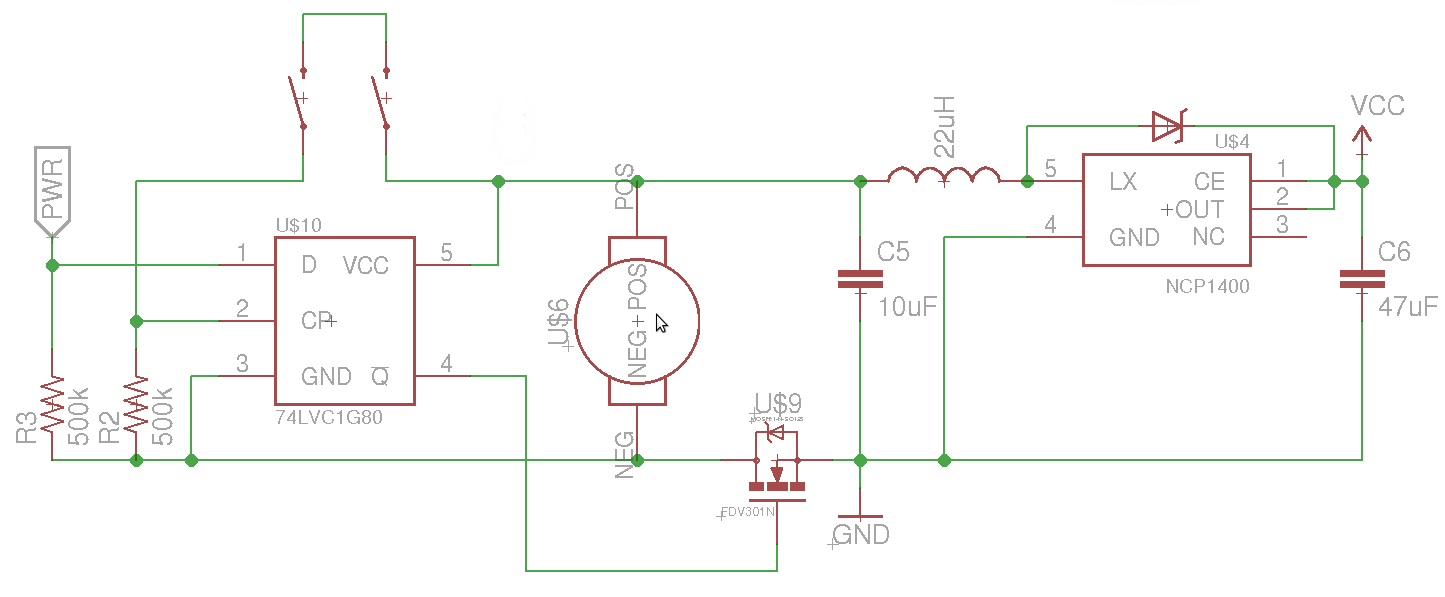
The objective is to control the power to a load, specifically an 8051-based microcontroller (uC), using two switches. When the uC is powered on, it sets the PWR pin high. Upon pressing the switches again, pin 4 of the...
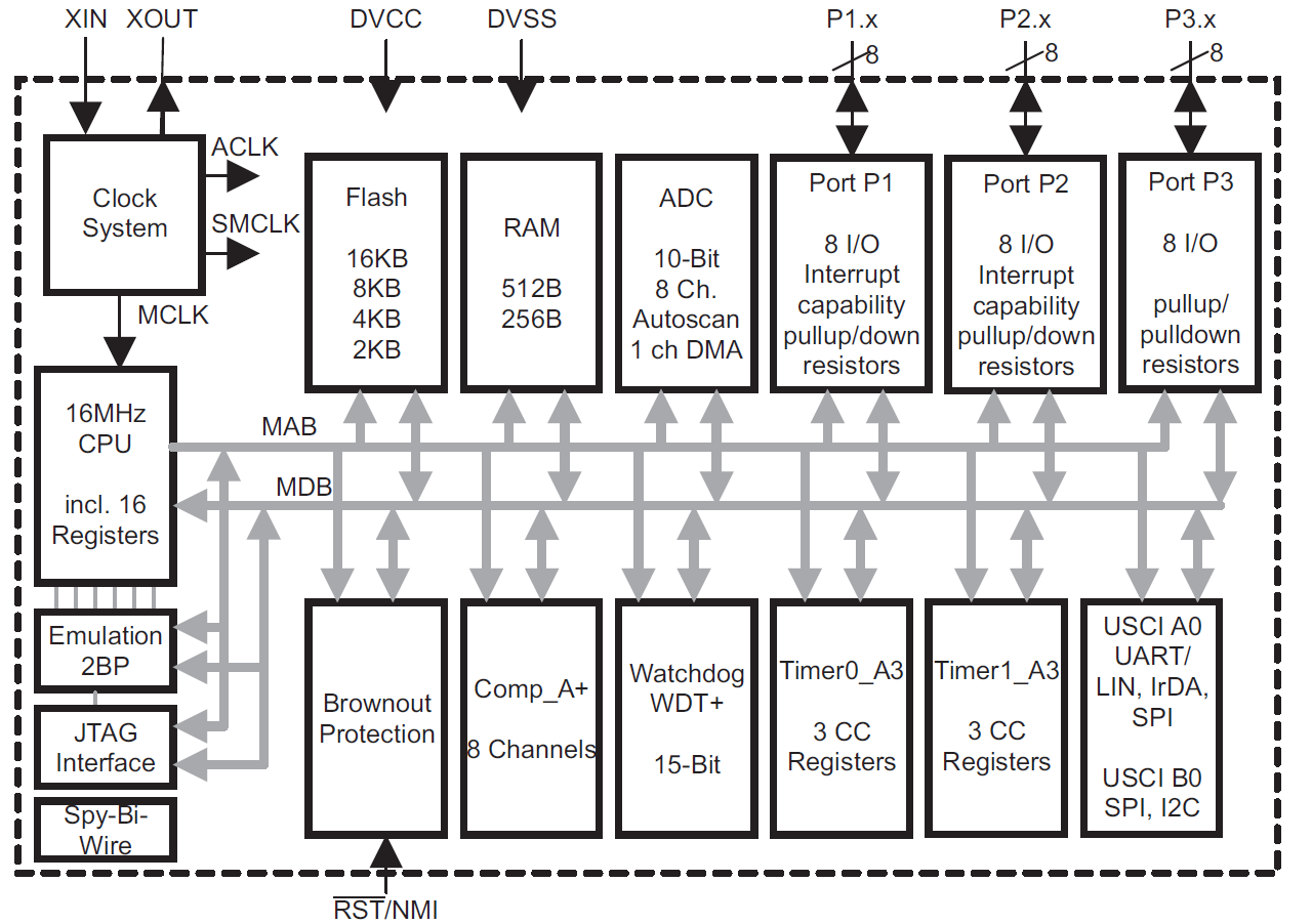
This module provides an overview of the MSP430 microcontroller, instructions on how to read its data sheet, and guidance on selecting the appropriate model for various applications. It is part of a textbook aimed at helping seniors choose Texas...
Motor Bike Headlight Controller Circuit. This circuit automatically turns a motorcycle's headlight on and off, independently of both the light and ignition switches, provided the battery is fully charged. The first stage... The motorcycle headlight controller circuit is designed to...