
Mosquito repeller power saver circuit and energy saver circuit diagram

The mosquito repellent power saver circuit is designed to efficiently operate a mosquito repellent device while minimizing energy consumption. This circuit typically integrates a microcontroller or a timer IC, which controls the activation and deactivation of the repellent device based on predefined intervals.
The schematic may include essential components such as resistors, capacitors, and transistors, which help in regulating the power supply and ensuring that the device operates within safe limits. A common configuration might involve a 555 timer IC, which can be set up in astable mode to generate a square wave output. This output can be used to drive a transistor that acts as a switch, turning the repellent device on and off at specified intervals.
Power supply considerations are crucial; the circuit may require a regulated DC source, often derived from an AC mains supply through a transformer and rectifier setup. Additionally, the use of a capacitor for smoothing the rectified voltage is typical to ensure stable operation.
For enhanced efficiency, the circuit design may incorporate features such as a low-power mode, where the microcontroller or timer IC consumes minimal energy during inactive periods. This approach not only prolongs the life of the power source but also reduces overall energy costs associated with the operation of the mosquito repellent device.
The layout of the circuit should be carefully designed to minimize interference and optimize the performance of the components. Proper placement of the components and routing of the connections are essential to ensure reliable operation and to prevent issues such as noise or voltage drops that could affect the functioning of the circuit.
Overall, this mosquito repellent power saver circuit serves as an effective solution for maintaining pest control while being energy efficient, making it suitable for both residential and commercial applications.The circuit diagram of a mosquito repellent power saver circuit is given with a detailed explanation.. 🔗 External reference
Related Circuits
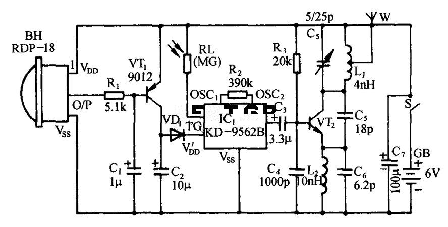
The circuit includes an infrared sensor head, electronic switches, an audible audio circuit, and an FM radio circuit. It is designed for installation in banks, treasuries, and other areas requiring supervision during evening hours in lieu of staff presence....
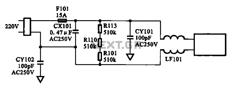
The AC input circuit consists of a fuse (Fl01), a mutual inductance filter (LF101), and filter capacitors (CX101, CY101, CY102), among other components. Its primary function is to filter out noise and pulse interference from the AC circuit, as...
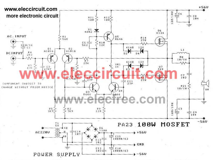
This circuit is a MOSFET power amplifier configured in an OCL (Output Capacitor-Less) topology. It delivers an output power of 100 watts and can utilize MOSFETs such as K134 and J49 or J162 and K1058. When driving an 8-ohm...
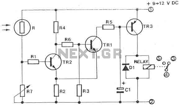
The circuit is a light switch that activates when the light intensity drops on a photoresistor. It features a straightforward construction and can be utilized in numerous applications. The photoresistor and the trimmer function as a voltage divider and...
The DTMF codec stands for dual-tone multi-frequency codec. The multiple-channel infrared remote control switch circuit that incorporates the DTMF is depicted in the figure. It consists of an infrared remote control signal emitter, an infrared receiving signal amplifier, a...
This 1 Hz and 2 Hz generator or oscillator is constructed using a 4060 IC as the oscillator and a 14-bit counter. To achieve a 1 Hz signal from the 4060, a 1/2 4013 flip-flop is utilized. This circuit...