
most common emergency sirens circuits
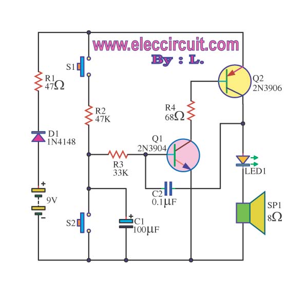
The siren circuit is a fundamental component in alarm systems, designed to provide audible alerts in various emergency scenarios. The schematic typically consists of two key transistors, Q1 and Q2, which are configured in a feedback loop to create an oscillating signal. Resistors R3 and R4 are used to set the biasing conditions for the transistors, ensuring they operate within their active regions. Capacitor C2 is critical for determining the frequency of the oscillation, which influences the pitch of the sound produced by the speaker.
When the circuit is powered, pressing switch S1 initiates the charging of capacitor C1. The voltage at the base of transistor Q1 rises, causing it to conduct. This action turns on transistor Q2, which allows current to flow through the speaker SP1, generating sound. The oscillation continues until C1 reaches its maximum charge, at which point the feedback loop is interrupted, and the sound ceases while the LED1 indicates the circuit's active state.
Upon releasing switch S1, capacitor C1 discharges through resistor R3 and transistor Q1, allowing the circuit to reset. This process can be repeated, resulting in a pulsing sound if S1 is pressed multiple times in quick succession. The design ensures that the siren is both effective and responsive, making it suitable for various applications where timely alerts are necessary. The careful selection of components, along with the arrangement of the circuit, contributes to the overall reliability and functionality of the siren circuit in alarm systems.The siren circuit is what importance in various alarm. For example : the emergency alert, burglar alarm circuits, Fire alarm circuits, Timer, sensor controls, etc. If we have not these circuit, We will not able to recognize the functionality of the circuit, we set out.
Operation of the circuit is Q1 and Q2 will work with R3, R4 and C2 is a frequen cy generator circuit with output connected to LED1 and speakers SP1. When I press the switch S1 to the C1 will begin to charge allows the voltage to pin B of Q1 increase other. The Q1 is working and Q2 is working with at the C1 charge full cycle will stop oscillator speaker is not.
The LED1 light and hold the release the pressure switch S1, resulting in C1 will start discharger through R3, Q1 to ground. The oscillator circuit sound Sirens in the lower out. If we press the switch S1 and then quickly leave many. The sound will be as continuous as C1 to charge and discharge alternately continuously. 🔗 External reference
Related Circuits
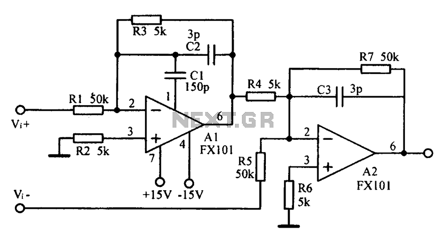
Common mode input voltage up to a difference of 100V enlarged circuit diagram. The circuit diagram described features a design capable of handling a common mode input voltage with a differential range of up to 100V. Such a configuration is...
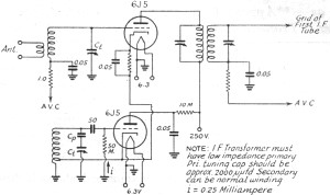
In 2011, designing a frequency converter circuit typically involves selecting an integrated circuit (IC) that meets specific requirements regarding gain and mixer spurious products, along with adding a couple of filters and a power supply. Often, the oscillator is...
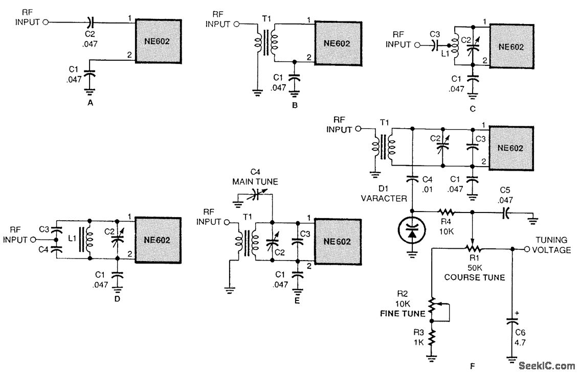
There are several methods to input a signal into the NE602. Simple untuned approaches (a and b) are viable. For tuning to a specific frequency, an LC resonant circuit with ungrounded trimmer capacitors (c and d) or grounded variable...

These circuits could be used as the basis for Model Railroad DCC Boosters or PWM motor controllers. The first schematic is for a basic 3 Amp - DCC Booster using the LMD 18200 CMOS, H-Bridge. Included in the design...
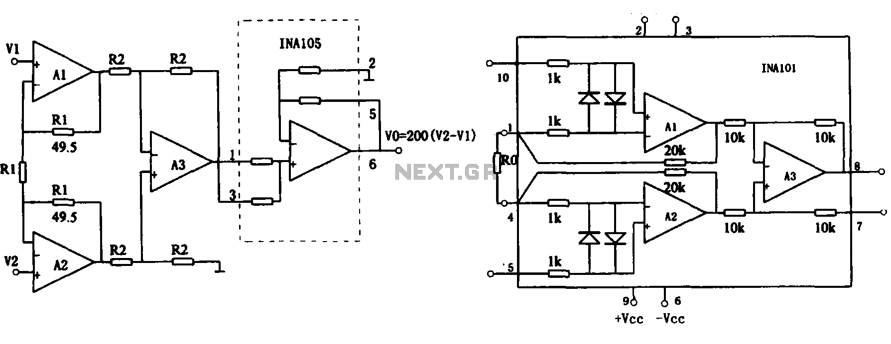
This document describes the extended common mode input voltage range of an instrument amplifier circuit. The circuit consists of three precision instrument amplifiers, A1, A2, and A3, which can be INA101 or INA102 models. The figure illustrates that A1,...
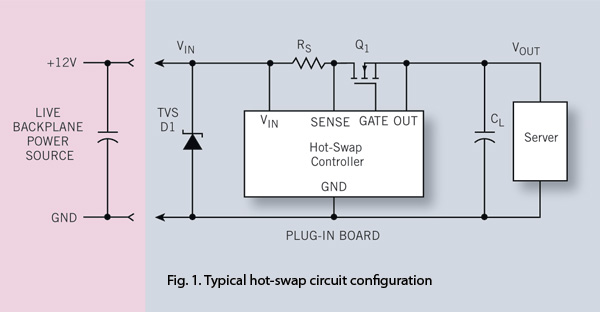
To ensure reliability, the server system designer must take into account the parasitics of hot-swap circuits and their associated transient behavior. It is recommended that a transient voltage suppressor (TVS) diode clamp be utilized at the line card input....