
Motion Detector

The motion detector circuit is designed to provide real-time detection of movement through a combination of infrared technology and a robust signal processing mechanism. The infrared emitting diode serves as the primary source of the infrared beam, which is essential for detecting interruptions caused by moving objects. The MRD821 sensor is sensitive to changes in the infrared light intensity, allowing it to output a high voltage when the beam is intact and a low voltage when the beam is interrupted.
The integration of the 555 timer is crucial for amplifying the sensor's output, converting the analog signal variations into a digital format suitable for further processing. The 555 timer operates in a comparator mode, where the voltage levels at its input pins determine the output state. When the infrared beam is continuous, the output remains low, indicating no motion. However, when an object crosses the beam, the output transitions to high, triggering the subsequent actions in the program.
The interfacing of the motion detector with a computer through the printer port allows for easy integration into various applications, such as security systems or automated lighting controls. The software component is responsible for monitoring the sensor outputs in real-time. The provided code snippet illustrates a function that checks the status of the sensors, incrementing the trigger count when at least two sensors detect motion. This ensures that false positives are minimized, as simultaneous activation of multiple sensors is required to confirm motion.
Overall, the motion detector circuit exemplifies a practical application of infrared technology combined with electronic signal processing, facilitating reliable detection of movement in a variety of environments. The addition of a de-amplifier can enhance the circuit's performance by stabilizing the output voltage levels, ensuring compatibility with digital systems.The motion detector circuit consists of two components, the emitter and the sensor/detector. The emitter is simply made up of an infrared emitting diode reverse biased to a 5-volt source. The sensor uses the MRD821 to detect the IR beam from the emitter. It outputs a high of around 9 to 10-volts when the IR beam shines directly to it. If the beam is cut, it outputs a low of around 0. 4 to 2-volts. This signal is fed into pins 2 and 6 of a 555 timer, which in turn outputs the amplified signal at pin 3. The output is a TTL low when the IR beam is continuous and TTL high when the beam is cut. (Actually, outputs of about 6 to 7-volts are sometimes measured. A de-amplifier could be added at the end of the circuit to make sure the output does not exceed TTL levels.
) The schematic diagram of both emitter and detector are shown in figure 1. There are three pairs of such sensors interfaced to the computer through the printer port. In order for motion to be sensed, a moving object must simultaneously trigger at least two of the detectors signifying that it has moved from one point to another. If the sensors have established motion, the controlling program proceeds to the appropriate routine. // IR Array Program Driver Program // Decoding is done via software int irmotion(){ int count=0, trigger=0, sensor=0; //initialize trigger & count flag int motion[3]={0x00, 0x00, 0x00}; //initialize array for sensor status outportb(0x37a, 0x08); //get mux`s attention outportb(0x37a, 0x08); //get mux`s attention do{ sensor=0; sensor=inportb(0x379); //get value at this port sensor=sensor & 0x70; //mask it motion[0]=sensor & 0x10; //assign status of each sensor motion[1]=sensor & 0x20; //as an element in motion array motion[2]=sensor & 0x40; if(motion[0]=0x10){ //at least 2 sensors must be triggered if(motion[1]=0x20 | motion[2]=0x40) //detect motion trigger+; } if(motion[1]=0x20){ if(motion[0]=0x10 | motion[2]=0x40) trigger+; //if motion is detected, trigger flag is incremented } if(motion[2]=0x40){ if(motion[0]=0x10 | motion[1]=0x20) trigger+; } count+; //increment count every pass to this function delay(30); }while(count!=2 && trigger!=2); return trigger; //if trigger=2, main function should //go to routine that deals with presence of intruder }
🔗 External reference
Related Circuits

The detector is designed to sense static charges and free ions present in the air. It can indicate the presence of ion emissions, high voltage, static electricity, and electrostatic fields. The grounding can be achieved through an earth ground...
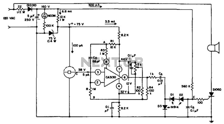
An ionization chamber in conjunction with a high-impedance CA3130 operational amplifier is utilized to detect the presence of smoke. When smoke is detected, the CA3130 ceases oscillation, which in turn triggers the S106D silicon-controlled rectifier (SCR) to sound an...

This circuit is designed for processing sonar data signals recorded on high-quality analog tape recorders. The envelope detector employs readily available components and provides accuracy exceeding 100 kHz. It utilizes two LM301 operational amplifiers configured as precision absolute-value circuits,...
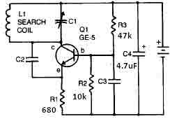
This metal detector circuit needs to be powered using a 9 volts power supply (DC) or a 9 volts battery. The C1 capacitor is a variable capacitor with a value of 365 pF, C2 is a 100 pF silver...
This simple circuit using a single transistor turns ON the relay when light falls on the LDR. The potentiometer is adjusted for the required sensitivity. The power supply is 6V. Be careful about the impedance of the relay. Its...

The basic operation of the monitor connected to the circuit is to detect objects (obstacles) at distances ranging from a few millimeters to several centimeters. This type of circuit is utilized in various industries and hospitals. The position sensor...