Motion Sensor For Security Light Using PIR BS1600 PCB

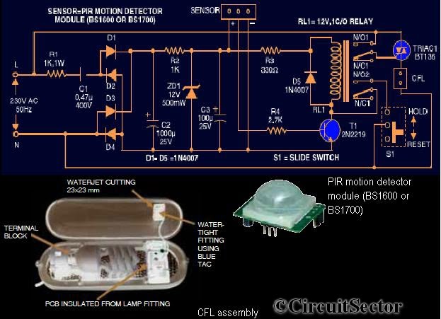
This circuit diagram is based on the PIR motion sensor module BS1600 (or BS1700) designed for security lighting in power-saving mode. If the component is unavailable in local stores, it can be purchased online. A key advantage of this motion detector circuit is that it does not require transformers in the power supply section. The 12V DC needed to power the motion sensor and drive the relay is derived directly from the mains supply. Upon powering the circuit after assembling all components, including the CFL, the CFL will illuminate for 10 seconds, turn off for 30 seconds, illuminate for another 10 seconds, and then turn off again. The circuit is then ready for operation. Any movement detected by the sensor module generates approximately 3.3V across the base of transistor T1, which serves as the relay driver, allowing it to conduct and activate relay RL1. Consequently, triac BT136 is triggered, delivering full 230V to illuminate the tube. If switch S1 is not held in position, the CFL will remain on for about 10 seconds as programmed in the sensor module.
The described circuit utilizes a Passive Infrared (PIR) motion sensor, which detects infrared radiation emitted by objects within its field of view, typically human bodies. The BS1600 or BS1700 modules are compact and efficient, making them suitable for various applications, including security lighting. The absence of transformers simplifies the design and enhances reliability, as it reduces the number of components that could fail.
The circuit operates by converting the AC mains supply into a usable DC voltage for the PIR sensor. This is typically achieved through a rectifier and smoothing capacitor, which ensures stable operation. The PIR sensor is configured to provide a low output signal when no motion is detected. Upon detecting motion, the output signal rises to approximately 3.3V, which is sufficient to turn on the transistor T1. This transistor functions as a switch, controlling the relay RL1 that connects the load (CFL) to the mains voltage.
The triac BT136 is employed in this circuit to handle the high voltage required to power the CFL. Once activated by the relay, the triac allows current to flow through the light source, thus illuminating it. The programmed timing (10 seconds on, 30 seconds off) is crucial for energy conservation, ensuring that the light only activates when necessary.
The switch S1 is included to provide manual control over the circuit, allowing the user to keep the CFL on if desired. If S1 is not pressed, the circuit will revert to its automatic mode, adhering to the programmed timing sequence. This design is particularly effective for security applications, where lighting is needed only in response to movement, thus optimizing energy consumption while maintaining safety and security.
Overall, this circuit is an excellent example of integrating simple components to achieve an efficient motion-activated lighting solution. The use of readily available parts and the straightforward design makes it accessible for both hobbyists and professionals in the field of electronics.Here`s the circuit diagram based on PIR motion sensor module BS1600 (or BS1700) that can be used for security lighting in power saving mode. (If you could not found one in your local store, buy PIR motion sensor online). The special advantage of this motion detector circuit is it doesn`t need any transformers in power supply section.
The 12V DC req uired for feeding the motion sensor and driving relay is derived directly from the mains supply. When you power-on the circuit after assembling all the components including the CFL, the CFL will glow for 10 seconds, turn off for 30 seconds, glow for 10 seconds and then turn off. Now the circuit is ready to work. Any movement across the sensor module is detected, about 3. 3V appears across the base of transistor T1 which is the relay driver and it conducts to activate the relay RL1.
Now the triac BT136 fires to provide full 230V and light up the tube. If the switch S1 is not in the hold position the CFL will be on about 10 seconds as programmed in the sensor module. 🔗 External reference


