
Digital voltmeter using ICL7107

The digital voltmeter circuit utilizing the ICL7107 is designed for precision voltage measurements in various applications. The ICL7107's architecture allows for efficient conversion of analog signals to digital readings, ensuring high accuracy and low power consumption. The dual-slope ADC technique employed in this circuit is particularly advantageous for minimizing the effects of noise and fluctuations in the input voltage, as it averages the voltage over a period of time.
In terms of the circuit layout, the integration process begins when the voltage to be measured is applied to the integrator, producing a linear ramp voltage. This ramp is then reversed by applying a known reference voltage, which helps in determining the time taken for the ramp to return to zero. This time interval is crucial, as it is directly proportional to the input voltage. The internal clock frequency, determined by R2 and C1, plays a significant role in ensuring the accuracy of the timing measurements.
The display configuration is designed for clarity and ease of reading. The rightmost three seven-segment displays are responsible for displaying the full range of digits, while the leftmost display indicates the sign of the measured voltage. The adjustment of resistor R4 allows the user to select different measurement ranges, enhancing the versatility of the voltmeter for various applications.
Overall, the circuit is a robust solution for accurate voltage measurement, suitable for educational, industrial, and laboratory environments. Its design emphasizes stability, accuracy, and user-friendliness, making it an excellent choice for anyone needing a reliable digital voltmeter.The circuit given here is of a very useful and accurate digital voltmeter with LED display using the ICL7107 from Intersil. The ICL7107 is a high performance, low power, 3. 5 digit analog to digital converter. The IC includes internal circuitry for seven segment decoders, display drivers, reference voltage source and a clock.
The power dissipation is less than 10mW and the display stability is very high. The working of this electronic circuit is very simple. The voltage to be measured is converted into a digital equivalent by the ADC inside the IC and then this digital equivalent is decoded to the seven segment format and then displayed. The ADC used in ICL7107 is dual slope type ADC. The process taking place inside our ADC can be stated as follows. For a fixed period of time the voltage to be measured is integrated to obtain a ramp at the output of the integrator.
Then a known reference voltage of opposite polarity is applied to the input of the integrator and allowed to ramp until the output of integrator becomes zero. The time taken for the negative slope to reach zero is measured in terms of the IC`s clock cycle and it will be proportional to the voltage under measurement.
In simple words, the input voltage is compared to an internal reference voltage and the result is converted in a digital format. The resistor R2 and C1 are used to set the frequency of IC`s internal clock. Capacitor C2 neutralizes the fluctuations in the internal reference voltage and increases the stability of the display.
R4 controls the range of the voltmeter. Right most three displays are connected so that they can display all digits. The left most display is so connected that it can display only 1 and -. The pin5(representing the dot) is connected to ground only for the third display and its position needs to be changed when you change the range of the volt meter by altering R4. (R4=1. 2K gives 0-20V range, R4=12K gives 0-200V range ). 🔗 External reference
Related Circuits
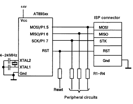
The AT89C family of microcontrollers features a parallel programming interface for flash memory. To write information, a programming voltage of 12V is required, and nearly all pins of the ports are utilized for this purpose. Consequently, parallel programming is...
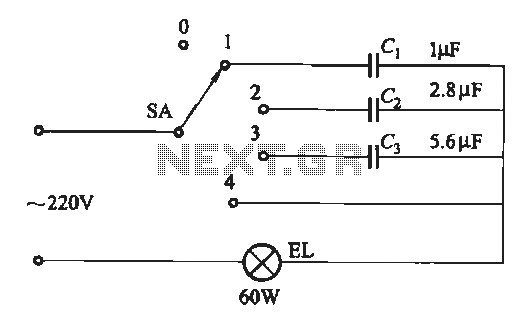
A dimming circuit capacitor circuit is illustrated in Figure 2-63. When the switch SA is moved from position "1" to "3," the capacitance increases in ascending order, resulting in the light bulb brightness also increasing correspondingly. When SA is...
This digital volume control has no pot to wear out and introduces almost no noise in the circuit. Instead, the volume is controlled by pressing UP and DOWN buttons. This simple circuit would be a great touch to any...
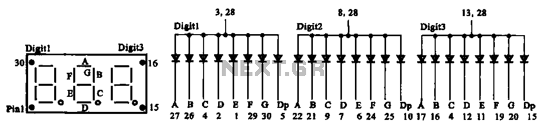
The document presents two types of digital display circuits. The first type (a) utilizes a common anode circuit configuration, while the second type (b) employs a common cathode circuit structure. The common anode display circuit configuration consists of multiple light-emitting...
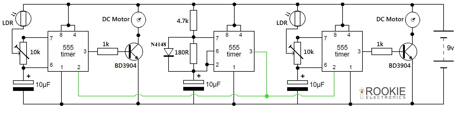
This is a simple and cost-effective approach to a line-following robot. It does not utilize any microcontroller but instead relies on a basic circuit composed of three 555 timers. The robot demonstrates good efficiency in following various curves and...
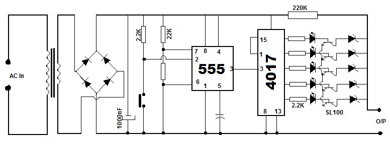
Battery eliminators are circuits that create a DC power supply from AC mains. Essentially, battery eliminator circuits consist of a step-down transformer, rectifier, and voltage regulator. A simple circuit of a multipurpose battery eliminator features various output voltage ranges...