
Motor speed control

The circuit employs the LM3524 integrated circuit, which serves as both a controller and driver for the DC motor. The LM3524 is a versatile PWM (Pulse Width Modulation) controller that can be utilized to regulate the speed of a DC motor by varying the duty cycle of the output signal. The output from the LM3524 drives a power transistor or MOSFET that controls the voltage supplied to the motor, thus enabling speed regulation.
The LM2907 is used as a speed sensor, providing feedback on the motor's rotational speed. The LM2907 operates as a frequency-to-voltage converter, translating the frequency of the motor's rotation into a proportional voltage. This feedback voltage is then fed back to the LM3524, allowing for closed-loop control of the motor speed. The feedback mechanism ensures that the motor speed can be adjusted dynamically based on the load conditions and desired speed setpoint.
In the schematic, the LM3524 is configured with necessary external components, including resistors and capacitors, to set the PWM frequency and to stabilize the control loop. The use of an appropriate power transistor or MOSFET is crucial for handling the motor's current requirements. The LM2907 is connected to the motor shaft, typically through a gear or a tachometer, to accurately sense the speed of the motor.
Overall, this circuit design provides an effective solution for controlling the speed of a DC motor with high precision and responsiveness, making it suitable for various applications in automation and robotics.This circuit is a regulating series dc motor speed control using the LM3524 for the control and drive for the motor and the LM2907 as a speed sensor for the feedback network.
Related Circuits
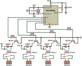
This is a relay driver based on a PIC16F84A microcontroller. The board includes four relays, allowing control of four distinct outputs. The relay driver circuit utilizing the PIC16F84A microcontroller is designed for controlling multiple devices or systems through relay activation....
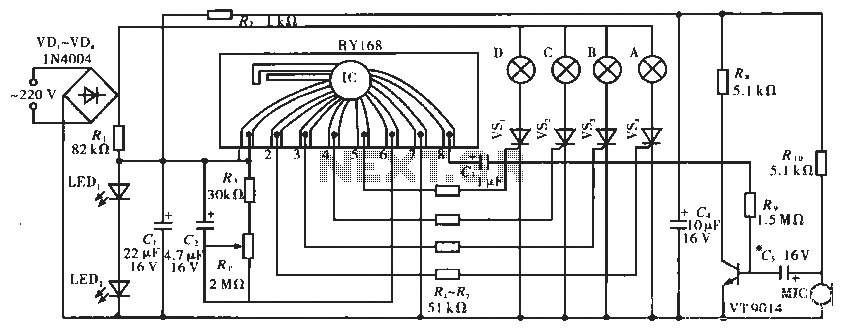
The circuit operates with a controller that includes a power supply circuit, a control circuit, and an audio amplifier, which are three distinct components. The power circuit comprises diodes VD1 to VD4, resistor R1, capacitor C1, LED1, LED2, and...
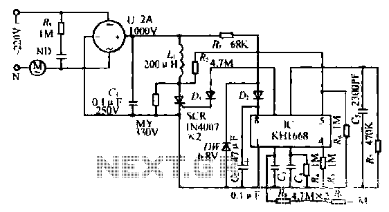
The synchronous vibration circuit operates with a control logic that includes three primary components. An internal oscillator is initiated by a synchronization pulse, transitioning to a low state immediately after the pulse. Upon power activation, the internal circuitry undergoes...
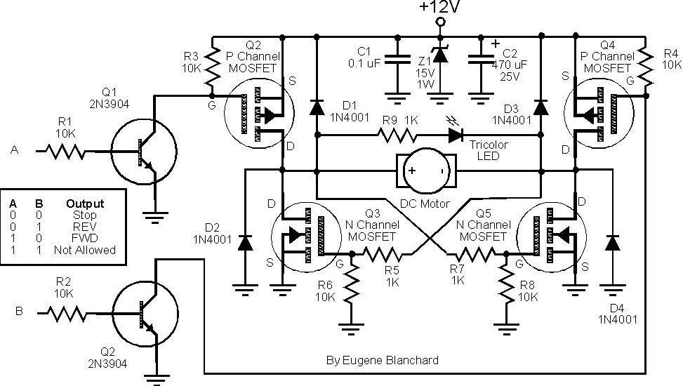
At 9 volts, the maximum stalled current of the motor types intended for use will be 700 mA. The selection of appropriate MOSFETs is crucial, particularly regarding their ratings for current and voltage handling. However, there are concerns about...
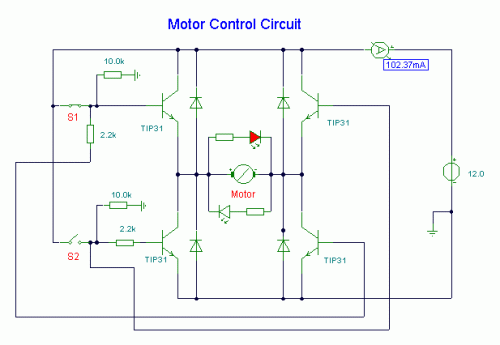
S1 and S2 are normally open, push-to-close, momentary switches. The diodes can be either red or green and are used solely for indicating direction. The TIP31 transistors may need to be adjusted based on the motor specifications. It is...
A modified piezoelectric ceramic acoustic-electric transducer is utilized to create a sound and light control system for a stairway walkway with a delay lighting switch. The circuit structure is relatively simple, consisting of diodes VD1 to VD4 and a...