
PIC16F84A Controlled Relay Driver

The relay driver circuit utilizing the PIC16F84A microcontroller is designed for controlling multiple devices or systems through relay activation. The PIC16F84A is an 8-bit microcontroller featuring 13-bit instruction architecture and a 14-bit program memory. It is well-suited for applications requiring logic control and output interfacing.
In this schematic, the microcontroller interfaces directly with four relays, which are typically electromechanical switches. Each relay is connected to a specific output pin of the microcontroller, allowing for individual control. The relays are powered through a suitable power supply, ensuring that the voltage and current ratings meet the requirements of the devices being controlled.
To drive the relays, the circuit incorporates transistor drivers. Each output pin from the PIC16F84A connects to the base of a transistor through a current-limiting resistor. When the microcontroller sends a high signal to the transistor, it allows current to flow from the collector to the emitter, energizing the relay coil. A flyback diode is placed in parallel with the relay coil to protect the circuit from voltage spikes generated when the relay is de-energized.
The design may also include additional components such as pull-down resistors to ensure stable operation of the microcontroller inputs and capacitors for filtering power supply noise. The board layout should be optimized for minimizing interference and ensuring reliable operation, particularly if the relays are controlling inductive loads.
Programming the PIC16F84A involves writing firmware that defines how the microcontroller responds to inputs, manages timing for relay activation, and ensures safe operation of the connected devices. The firmware should also include debounce logic if mechanical switches are used as inputs to prevent false triggering of relays.
This relay driver circuit is applicable in various automation projects, including home automation, industrial control systems, and remote device management, providing a robust solution for controlling multiple outputs efficiently.This is a relay driver that is based on a PIC16F84A microcontroller. The board includes four relays so this lets us to control four distinct .. 🔗 External reference
Related Circuits
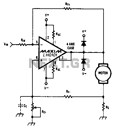
When the torque load on the motor increases, its current also rises. This increase in current is detected across Rs, and positive feedback is applied to the noninverting terminal of the LH0101, which in turn raises the motor voltage...
The LM1036 is a DC-controlled circuit designed for tone adjustment (bass/treble), volume control, and balance. It is suitable for use in car radios, televisions, and audio systems. The circuit also incorporates loudness compensation. The LM1036 integrates several functionalities essential for...
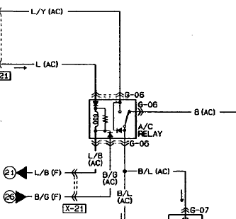
An automotive relay is being analyzed, which exhibits a more complex wiring configuration than typical relays. The diagram indicates that the B/G line maintains a high signal if certain conditions are met, specifically when the engine temperature is excessively...
Schematic of Big Trak's motor driver circuit. The toy includes 9112 and 9113 transistors (and sometimes 2N6715) because the 75494 chip cannot supply enough current to run the Big Trak's motors by itself. The motor driver circuit for the Big...
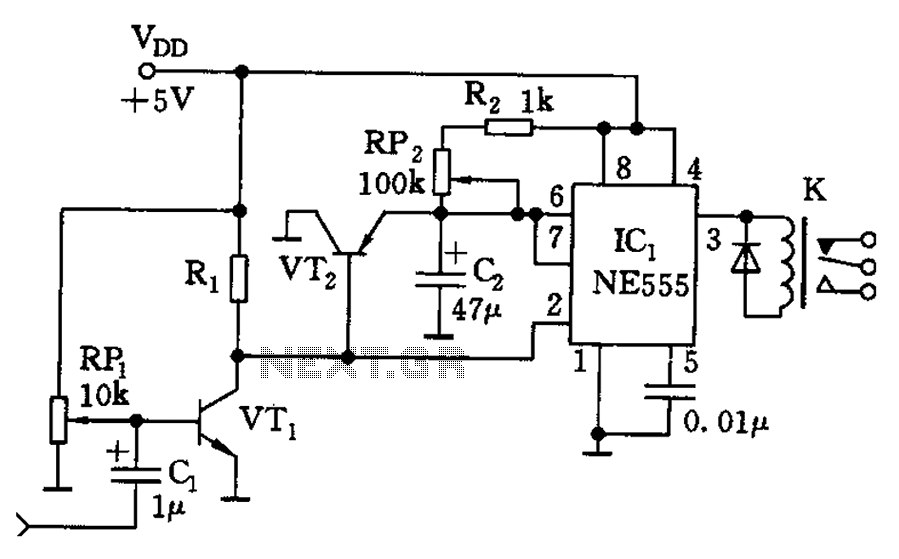
The circuit consists of a sound detection circuit and a monostable trigger circuit that activates a relay. VT1 amplifies the input audio signal. When a signal is detected, the 555 timer is triggered, pulling K. Simultaneously, VT2 conducts, allowing...
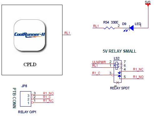
The CoolRunner-II board features external 5V relay interfacing, as indicated in the accompanying figure. The ULN2803 is utilized as a driver for the CPLD I/O lines, with the driver outputs connected to the relay modules. A PTB connector is...