
Motor Speed Control Using PWM

PWM operates by varying the width of the pulses in a signal while maintaining a constant frequency. This method allows for precise control of the average power delivered to an electrical device by adjusting the duty cycle, which is the ratio of the "on" time to the total cycle time. For instance, a 50% duty cycle means the signal is on half of the time and off the other half, resulting in an average power output that is half of the maximum.
In practical applications, PWM is widely used in motor speed control, dimming of lights, and in various power supply circuits. The implementation of PWM in motor control enables smooth acceleration and deceleration, reduces mechanical wear, and enhances energy efficiency. The use of high-frequency PWM signals minimizes audible noise in motors, as the switching frequency is typically above the audible range.
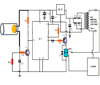
To design a PWM circuit for motor control, a microcontroller or a dedicated PWM controller can be employed. The microcontroller generates the PWM signal based on the desired speed input, which can be adjusted via a potentiometer or a digital interface. The PWM signal is then fed into a power stage, typically comprising a MOSFET or an IGBT, which acts as a switch that controls the motor's power supply.
The circuit should include protective components such as diodes to prevent back EMF from damaging the switching elements, as well as capacitors to filter voltage spikes. Feedback mechanisms, such as tachometers or encoders, can be integrated to provide real-time speed data, allowing for closed-loop control and further refinement of the PWM signal based on the motor's performance.
Overall, PWM stands as a versatile and efficient method for power regulation in various electronic applications, particularly in the control of electric motors.Pulse width modulation or familiarly known as PWM is used to control the delivered power to load without loosing the efficiency. The speed of an electric motor.. 🔗 External reference
Related Circuits
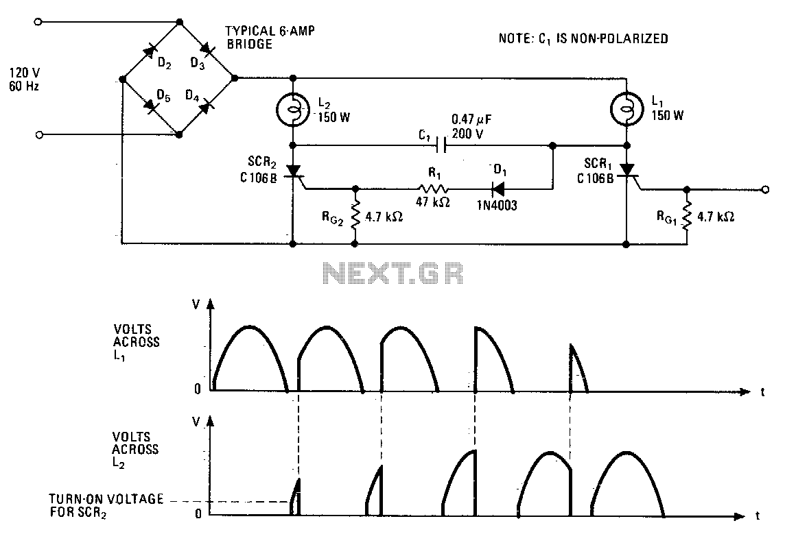
This lighting control unit will gradually decrease the brightness of one lamp while simultaneously increasing the brightness of another. The two loads maintain precise tracking without the need for manual adjustments. The gate of SCR1, a silicon-controlled rectifier, is...
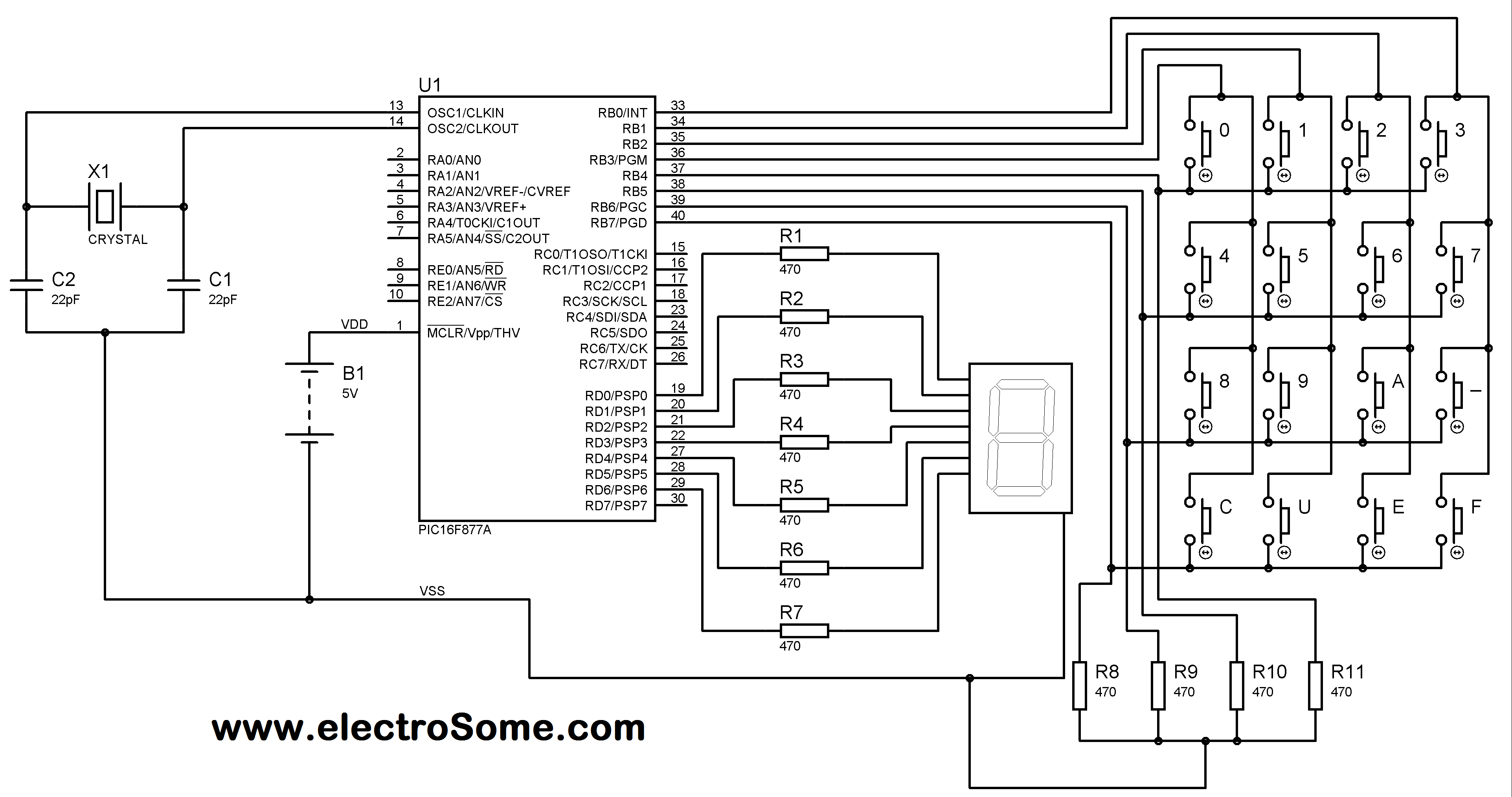
A matrix keypad is a highly useful and user-friendly component in the design of applications such as calculators and telephones. It consists of push-button switches arranged in rows and columns. For instance, interfacing a 4x4 (16 keys) matrix keypad...
A pulse motor, commonly known as a stepper motor, is defined as a motor that changes its excitation state according to input pulse signals, allowing it to move forward at a specific angle or distance. If the excitation state...
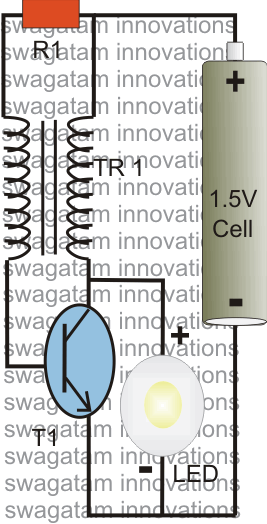
The post explains a simple 1 watt LED driver circuit using a single 1.5 V penlight cell through the joule thief concept. The coil may be wound over a T13 toroidal ferrite core using 0.2 mm or 0.3 mm...
Modern ICON electronic engine controls from BRP The ICON electronic engine control system developed by Bombardier Recreational Products (BRP) represents a significant advancement in marine technology. This system integrates sophisticated electronic controls to enhance the performance and reliability of marine...
The following post illustrates a simple light-operated remote control circuit that can be activated by an ordinary flashlight or, more effectively, through a laser beam unit (keychain type). The Light Dependent Resistor (LDR) is connected between the base of...