
Motor speed controller with timer 555

Pulse Width Modulation (PWM) is a widely used technique in electronics for controlling the power delivered to electrical devices. The fundamental principle involves varying the duty cycle of a square wave signal, allowing for precise control over analog devices such as motors and lights. In a typical PWM circuit, a square wave is generated with a frequency that can be adjusted according to the application requirements. The width of the pulse within this wave is modulated, which effectively changes the average voltage and current supplied to the load.
In a dimmer circuit, for instance, the PWM signal is employed to adjust the brightness of a light source. By varying the pulse width from 5% to 95%, the circuit can achieve a range of light intensities. At a 5% duty cycle, the light appears dimmed significantly, while at a 95% duty cycle, it operates at full brightness. Similarly, in motor speed control applications, the PWM signal regulates the motor’s speed by altering the power delivered to it. A low duty cycle (5%) results in low speed, while a high duty cycle (95%) allows the motor to reach its maximum speed.
The circuit components required for constructing a basic PWM controller include a 1kΩ resistor, a 1mF tantalum capacitor, two 1N4148 diodes, a 100kΩ variable resistor, and a 555 timer IC. The 555 timer operates in astable mode to generate the PWM signal. The variable resistor allows for manual adjustment of the duty cycle, enabling users to fine-tune the output as needed.
The use of diodes in the circuit serves to protect against reverse voltage and enhance the performance of the PWM signal. Additionally, the choice of capacitor can influence the circuit's filtering capabilities, which is crucial for minimizing radio frequency interference (RFI) that may arise from the rapid switching of the PWM signal. In some cases, replacing the tantalum capacitor with a different type may help reduce RFI further.
In summary, PWM is a versatile method for controlling power in electronic circuits, with applications ranging from lighting to motor control. The careful selection of components and attention to circuit design can optimize performance and mitigate potential issues such as interference.Pulse width modulation (PWM) is a technique to control analog circuits with a digital output. PWM is used in many applications, Specially to control light intensity and speed on motors. A PWM circuit makes a square wave with a variable width. The pulse width in this circuit can be varied from 5% to 95%. Used in a dimmer, this circuit controls the light intensity according the pulse width. On speed controller, the power of the motor depends the width from 5% (low power/speed) to 95% (full power/speed). The main disadvantage of this circuit, as all PWM circuits, is the possibility of generating radio frequency interference (RFI).
It can be reduced changing the capacitor.
Parts needed: * 1 1k Resistor * 1 1mF Capacitor (Tantalium capacitors works great) * 2 4148 Diodes * 1 100k Variable resistor * 1 IC 555 oscillator. Germanium diodes can be used to increase the range of the PMW up to 1% to 99%.
🔗 External referenceRelated Circuits
I ride my bike allot at night and sometimes I'm not sure if people can see me. This circuit will flash an incandescent light that you can purchase from Radio Shack. Adjust the VR's for your flash requirements and...
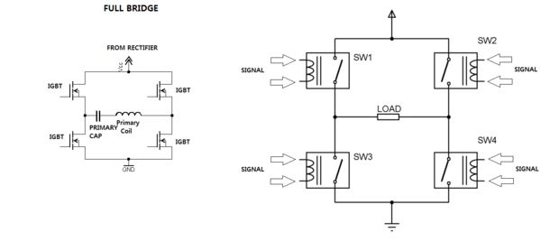
One of the most challenging aspects of constructing a solid-state Tesla coil is the bridge or switching circuit. The bridge switching circuit is the core component of the system. The bridge switching circuit is essential for controlling the power delivery...
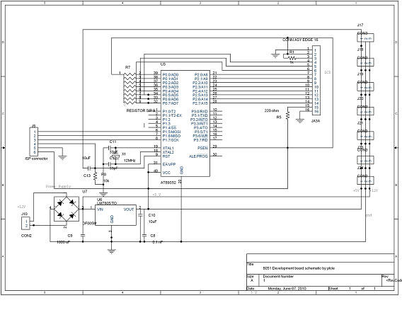
DTMF-based Robo Car design using the 8051 microcontroller project. This project demonstrates a method to control a domestic system using the DTMF tone generated by a telephone instrument when the user presses the keypad buttons of a mobile phone...
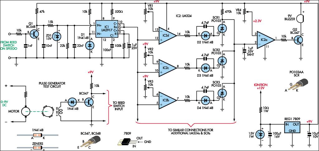
In normal suburban driving, passing through various speed zones can make it cumbersome to switch speed settings. The speed display may also serve as a distraction. This circuit removes the display and the need for speed selection altogether. Each...
Application note on designing linear and switch-mode (switching DC-DC converter current source) battery charger applications that require external microcontrollers and related system-level issues for notebook computers. The application note provides guidance on the design of both linear and switching DC-DC...
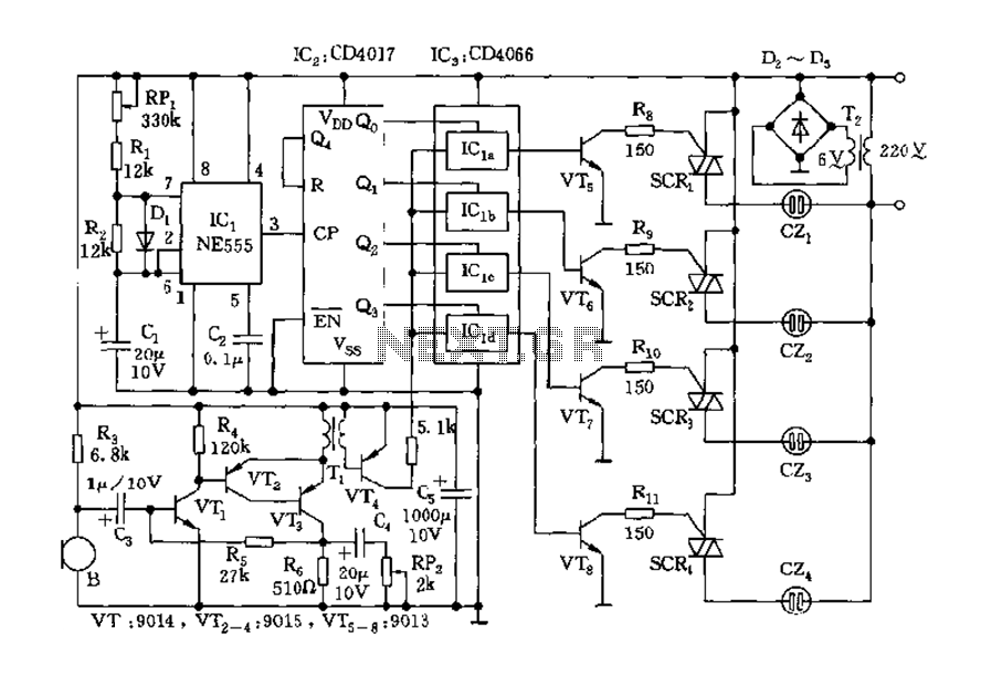
The circuit includes a controller that integrates an acoustic-electric conversion and amplification circuit, a clock pulse generator, a counting circuit, and a control circuit. It manages four accompanying music tracks and flashing lights. Microphones (MIC) convert sound into electrical...