
Motorcycle anti-theft lock electronic circuit

The 5C058 ASIC lock circuit is designed for secure access control applications. It utilizes a sequence of valid key inputs to unlock, ensuring that only authorized users can gain access. The valid key inputs are connected to pins 1 through 6, which are linked to a key switch mechanism. When the correct sequence of keys A through F is pressed, the circuit recognizes the input and activates the unlocking mechanism.
The negative power supply is connected to pin 7, which ensures that the circuit has a common ground reference, essential for stable operation. The false key input terminal at pin 8 is a critical feature that enhances the security of the lock. This terminal can be connected to an invalid key switch, allowing the circuit to identify and disregard spurious inputs that do not conform to the valid key sequence.
The circuit's ability to accept mixed inputs is a unique feature that provides flexibility in operation. Users can press multiple keys simultaneously or in quick succession without triggering a false unlock response. This design consideration is important in environments where security is paramount, as it prevents unauthorized access through accidental or unintentional key presses.
Overall, the 5C058 ASIC lock circuit represents a robust solution for electronic locking mechanisms, combining ease of use with advanced security features to protect sensitive areas or devices.Circuit works: lC1 is lock ASIC 5C058. Its 1-6 feet were even outside the key switch to the positive power supply, which is six valid key input, open lock A-F must comply with this order. 7 feet for the negative power. 8 feet false key input terminal, even outside an invalid key switch. You can take one or several mixed into the keyboard in order to leave spurious.
Related Circuits
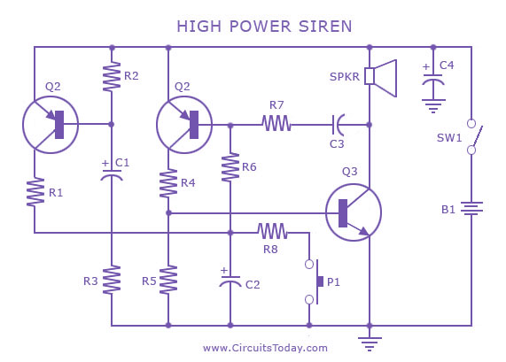
A siren circuit diagram that generates a strong, high-power siren or alarm sound using complementary transistor pairs BC 557 and BC 337, arranged as an oscillator. The described siren circuit employs a pair of complementary transistors, BC 557 (a PNP...
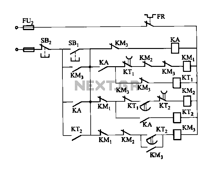
Figure 3-118 illustrates an automatic acceleration control circuit. This circuit employs a male contactor time relay, enabling the motor to start automatically at a low speed before transitioning to high-speed operation. The automatic acceleration control circuit depicted in Figure 3-118...
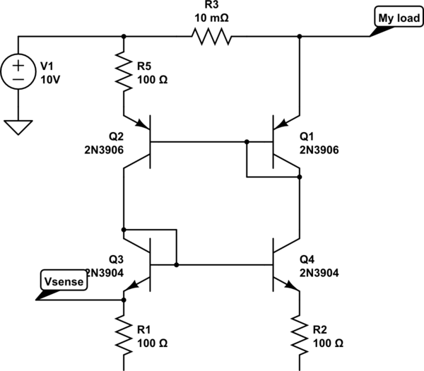
The bases and emitters of the transistors are connected together, resulting in equal base-emitter voltages. Assuming the transistors are identical, equal Vbe leads to equal base currents, which in turn results in equal collector-emitter currents. By adjusting the voltage...
This circuit will impose a maximum slew rate on a signal; positive and negative rates can be independently controlled. The circuit is useful in servo applications where the error signal needs to be limited to be within the power...
This circuit is a motion detection sensor that utilizes a light source and detector as an infrared motion detector. The motion sensor employs an infrared LED and a phototransistor. Since it relies on light, the sensor's sensitivity can be...
The metal detector circuit is shown here that the limits represent the sake of simplicity for a metal detector, but the design works remarkably well. It only uses 40,106 Hex Schmitt inverter IC, a capacitor and a search coil...