
CIRCUIT ALLOWS SLEW RATE CONTROL

The described circuit functions as a slew rate limiter, which is critical in various electronic applications, particularly in servo control systems. The primary objective of this circuit is to restrict the rate of change of the output signal, thereby preventing abrupt changes that could lead to instability in the system.
The circuit typically consists of operational amplifiers (op-amps), resistors, and capacitors configured in such a way that the output signal's rise and fall times are controlled. The op-amps are arranged to compare the input signal with a feedback signal derived from the output. By adjusting the feedback loop, the maximum slew rate can be set for both the positive and negative transitions of the signal independently.
For instance, the positive slew rate can be controlled by a resistor-capacitor (RC) network that determines how quickly the output can rise when the input signal transitions from a low to a high state. Similarly, a separate RC network can be used to control the negative slew rate, allowing for tailored performance based on application requirements.
In practical applications, this circuit is implemented to ensure that the servo system does not exceed the limits of the power supply rails. By limiting the slew rate, the circuit enhances the stability and predictability of the servo response, minimizing overshoot and oscillations that could occur if the system were allowed to respond too quickly to changes in the input signal.
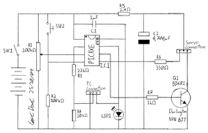
In summary, this circuit serves an essential role in maintaining controlled signal transitions in servo applications, promoting reliable operation within the defined power limits.This circuit (figure 1) will impose a maximum slew rate on a signal; positive and negative rates can be independently controlled. The circuit is useful in servo applications where the error signal needs to be limited to be within the power rails to ensure predictable operation.
🔗 External reference
Related Circuits
The output frequency can be altered based on the division ratio of the comparison frequency in the 10 kHz unit, with the division ratio set to 1024 in this circuit. Given that the amateur radio bandwidth in Japan is...
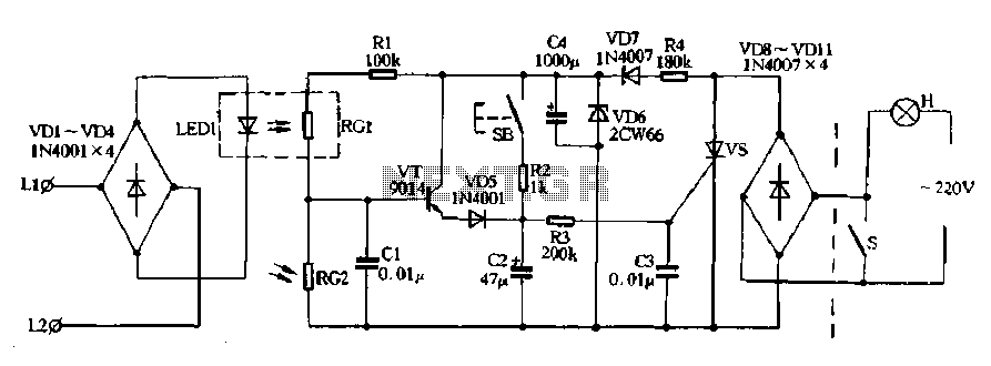
Diodes VD8 to VDI1 function as part of the main circuit isolation, with SCR serving as a composition control switch. The buck regulator circuit is composed of a stable orbital tube VD6 and a simple resistor-capacitor combination (C4). The...
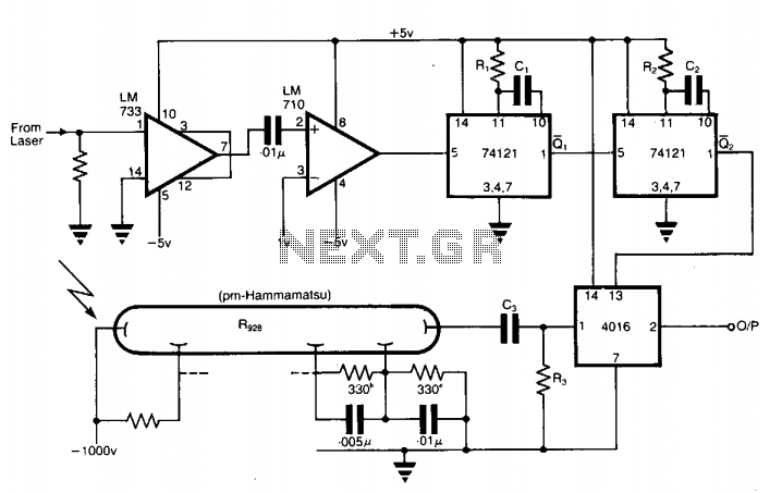
The application involves observing the light pulse emerging from a thick specimen after transillumination by a laser pulse. Pulses derived from the laser source are amplified using a Video Amplifier LM733. The reference level is set to 1 V...
Touch controls are not only utilized for switching devices on or off but can also manage various functions. A notable example is the TV remote control. When it is crucial to maintain activated functions for an extended period, employing...
This circuit utilizes a sawtooth oscillator along with an output amplifier that drives a transistor. The components C1, C2, and L1 are essential for the oscillator's operation, forming a tank circuit that must be tuned to the resonant frequency....
This project involves creating a programmable camera controller using basic hand tools and a digital camera. By utilizing components that are commonly found at home, the overall costs can be minimized. A servomotor can be repurposed from a radio-controlled...