
motorcycle low voltage warning

The motorcycle battery monitoring circuit is designed to prevent battery drain due to accessories remaining powered when the ignition is off. The circuit employs two operational amplifiers configured as comparators. The first comparator monitors the battery voltage and is set to trigger when the voltage drops below a predefined threshold, typically around 11.5 volts for a 12-volt system.
Upon detection of low voltage, the first comparator activates transistor Q1. This transistor serves as a switch that connects capacitor C1 to the power supply, allowing it to charge. The capacitor acts as a timing element, and its charging time is determined by the resistor-capacitor (RC) time constant formed with the associated components. The charging process typically takes 6 to 8 seconds, which is sufficient to allow transient voltage drops (such as those occurring during engine cranking) to pass without triggering the alarm.
Once the voltage across capacitor C1 reaches the reference voltage set by the zener diode, the second comparator activates the beeper. The beeper serves as an alert mechanism, notifying the user of the low battery condition. The design ensures that the beeper will not sound while the starter is engaged, as this would create false alarms during normal operation.
The circuit's design is compact and can be integrated into existing motorcycle wiring without significant modifications. It is essential to select components with appropriate ratings to handle the motorcycle's electrical environment, ensuring reliability and durability. Proper placement of the circuit is critical to avoid exposure to moisture and vibrations, which are common in motorcycle applications. This circuit effectively enhances the reliability of the motorcycle by preventing inadvertent battery drain, thereby improving user experience and reducing the risk of being stranded due to a dead battery.This circuit is connected to your motorcycle. It`s tapped into a circuit thats only powered with the key "ON". If you turn the bike off with the kill-switch and leave the key on, as you know, the headlight will stay on and quickly drain the battery. With this circuit, once system voltage is down a volt and a half or so, the first comparator turns on Q1. Q1 begins charging capacitor C1. After about 6-8 seconds, the voltage on C1 equals the reference zener voltage and the second comparator turns on the beeper. This way the low voltage condition must be sustained, i. e. won`t start chirping while cranking the starter, but still goes off soon enough to keep you from getting too far from your bike.
Thanks R. P! 🔗 External reference
Related Circuits
Safety devices like fuses provide protection against excess current, but do nothing for transients and short duration spikes of high voltage on the power supply lines. This circuit uses the "crowbar" method and provides fast protection against transient voltage...
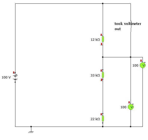
A user is utilizing YENKA software to diagram circuits but is experiencing confusion regarding the voltage calculations in a basic series circuit, as illustrated in the attached image. In a basic series circuit, components are connected end-to-end, forming a single...
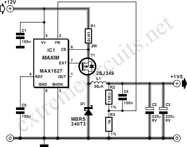
Most small internal combustion engines commonly used in model building utilize glow plugs for starting. However, glow plugs operate at a voltage of 1.5 V, while components such as fuel pumps, starter motors, and chargers typically operate at 12...
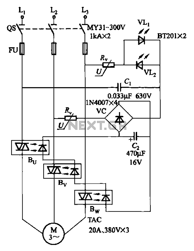
The circuit depicted in Figure 3-93 is integrated with an optical phase sequence protection relay. The circuit in question is designed to provide phase sequence protection using an optical relay mechanism. Optical phase sequence protection relays are crucial in applications...
A filter removes the DC component of the rectified AC, which is then scaled to RMS. The output is linear from 40 Hz to 10 kHz or higher. The described circuit primarily consists of a filter designed to eliminate the...
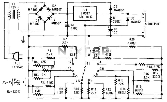
This supply can function as a battery eliminator for various devices, such as tape recorders, small radios, clocks, and more. A resistance is selected to provide a predetermined output voltage. In this circuit, various commonly used supply voltages produced...