
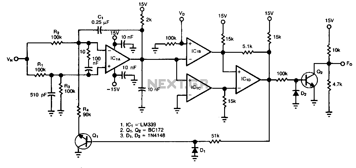
Current-to-voltage converter

The described circuit primarily consists of a filter designed to eliminate the direct current (DC) component from a rectified alternating current (AC) signal. This is typically achieved using a combination of capacitors and resistors configured in a low-pass filter arrangement. The purpose of this filter is to allow the alternating current component of the signal to pass while blocking any DC offset, thereby ensuring that the output signal accurately represents the AC waveform without any DC bias.
After the filtering process, the signal is scaled to represent its root mean square (RMS) value, which is a crucial measurement in AC signal processing. The RMS scaling can be performed using an RMS-to-DC converter, which provides a stable output voltage proportional to the RMS value of the input AC signal. This conversion is essential for applications where accurate power calculations or signal analysis are required.
The circuit’s output is specified to be linear across a frequency range from 40 Hz to 10 kHz or higher. This linearity indicates that the filter and scaling circuitry can accurately reproduce the input signal characteristics within this frequency range, making the circuit suitable for audio applications, signal processing, and other electronic systems where fidelity of the AC signal is critical. The ability to maintain linearity over this range ensures minimal distortion and accurate representation of the original signal, which is vital for high-quality audio and precise measurements in various electronic applications.A filter removes the dc component of the rectified ac, which is then scaled to RMS The output is linear from 40 Hz to 10 kHz or higher.
Related Circuits
The circuit accepts two positive voltage inputs, VN and Vv, and provides a TTL-compatible output pulse train whose repetition rate is proportional to the ratio VN/V0. The full-scale output frequency is approximately 100 Hz, and the linearity error is...
The circuit was designed to create a frequency converter using a crystal oscillator for the conversion of 10 MHz to 1 MHz. It incorporates a 7404 hex inverter. The circuit functions as a frequency divider, utilizing a crystal oscillator to...
Various values of D3 can be utilized to achieve different output voltages ranging from approximately 0.6V to around 30V. It is important to note that at elevated voltages, the circuit's performance may diminish, potentially resulting in lower current output....

The current circuit is designed to convert sinusoidal input signals into TTL output signals. It is capable of handling input signals greater than 100 mV and operates effectively at frequencies up to approximately 80 MHz. Transistor T1 is configured...
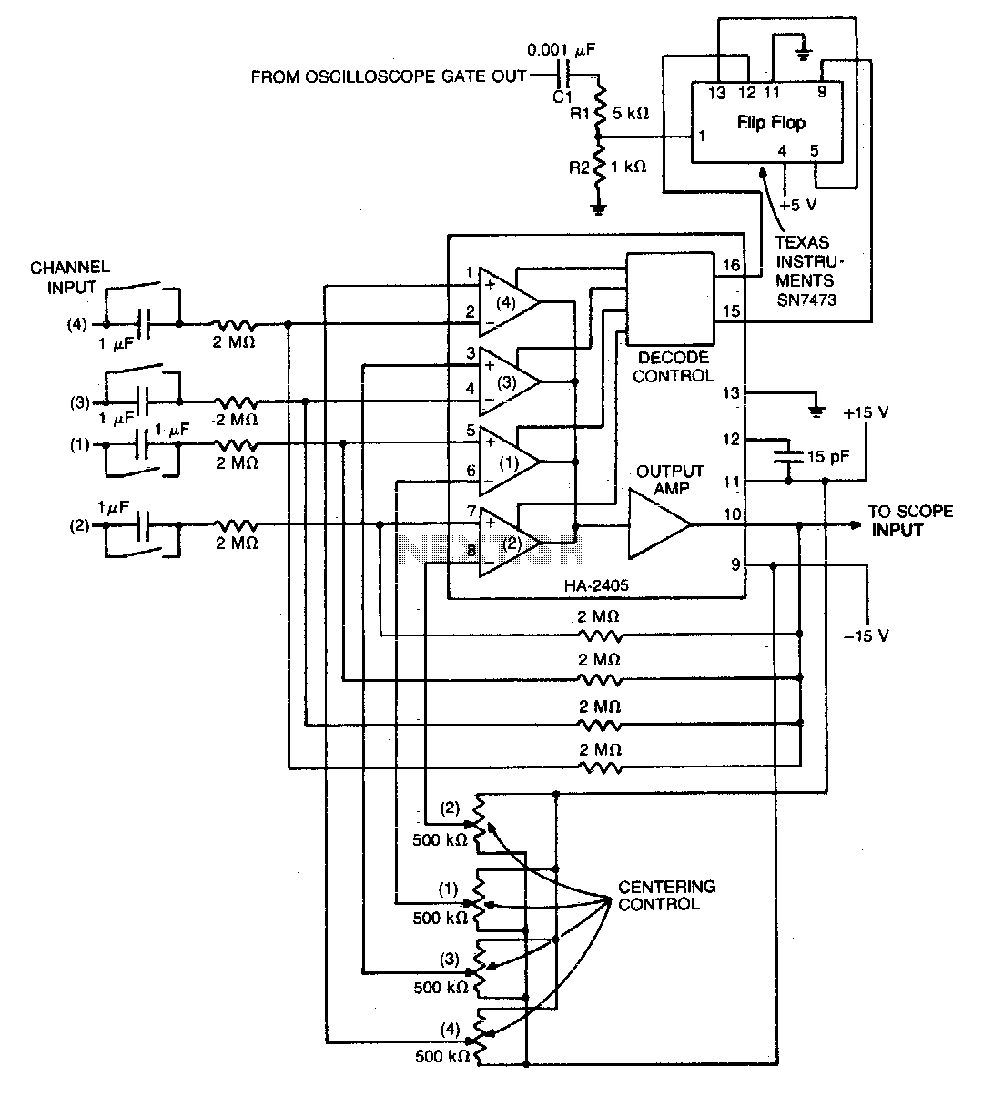
The monolithic quad operational amplifier offers a cost-effective solution for enhancing the display capabilities of a standard oscilloscope. Binary inputs control the integrated circuit operational amplifier, while a dual flip-flop divides the oscilloscope's gate output to generate channel selection...
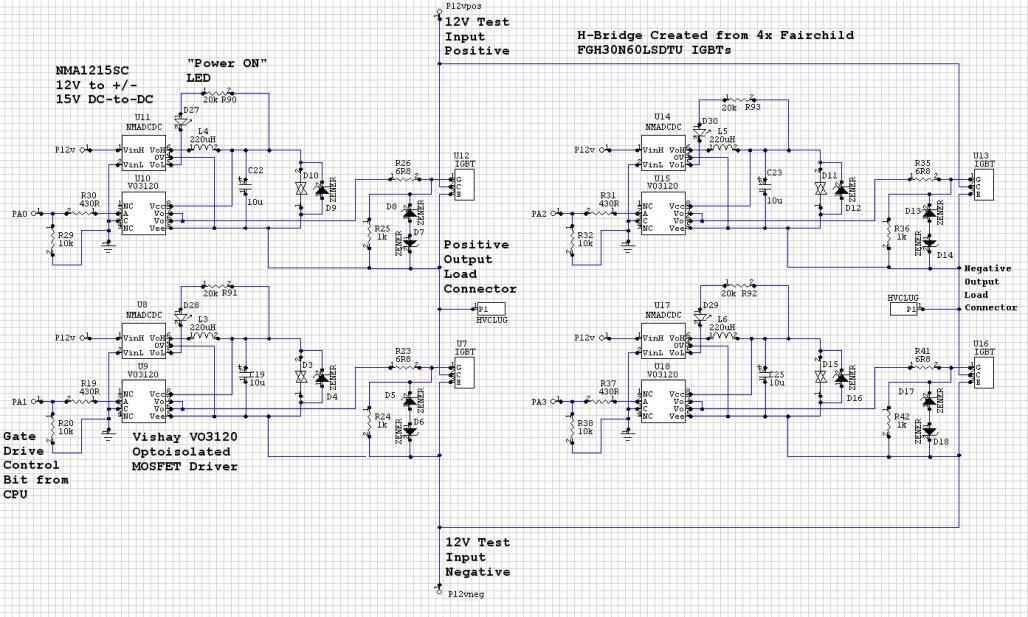
The Murata NMC1215SC DC/DC converters in a CPU-controlled H-Bridge design are experiencing repeated failures, with no obvious signs of the cause. The Murata NMC1215SC is a step-down DC-DC converter renowned for its efficiency and compact design, making it suitable for...