
motorola hi fi power

To ensure optimal performance of the amplifier circuit, it is crucial to accurately measure the hfe values of the transistors T3 and T4. The hfe, or current gain, is a vital parameter that influences the overall gain and fidelity of the amplifier. When selecting transistors, a tolerance of less than 30% between the hfe values is recommended to maintain sound clarity. The use of MJ3001 and MJ2501 transistors, known for their reliability in audio applications, resulted in a minimal deviation of approximately 5%, which is acceptable for high-quality sound reproduction.
Prior to powering the amplifier, it is essential to short-circuit the input to prevent any unwanted signals from affecting the initial measurements. Connecting a milliampere meter to the output allows for precise monitoring of the DC output current. Upon powering the amplifier, the R13 potentiometer must be adjusted carefully. This adjustment is critical for minimizing the DC offset at the output, which could otherwise lead to distortion or damage to connected speakers. The goal is to achieve a DC output current as low as possible, ideally reaching zero. In this case, a successful adjustment was made, reducing the current to 10 microamperes, which indicates that the amplifier is functioning correctly without significant DC offset.
In summary, following these procedures ensures the amplifier operates within its designed specifications, contributing to clear and accurate sound reproduction. Proper transistor matching and meticulous adjustment of the output current are essential steps in the amplifier setup process.The first thing that you must do, is to measure the end transistors (T3 and T4) amplifying coefficient, the hfe or ². If their disagreement is bigger than 30 %, the amplifier would not give a clear sound. I used MJ3001 and MJ2501 transistors, and this disagreement was around 5%. - Before the first ½turning on ½ you must short circuit the input s of the amp, and put a mA-meter on the output, than turn the amplifier on, and tune the R13 pot, to decrease the DC current on the output, to some uA-s, or in a lucky situation to zero. I was able to decrease it to 10 uA. 🔗 External reference
Related Circuits
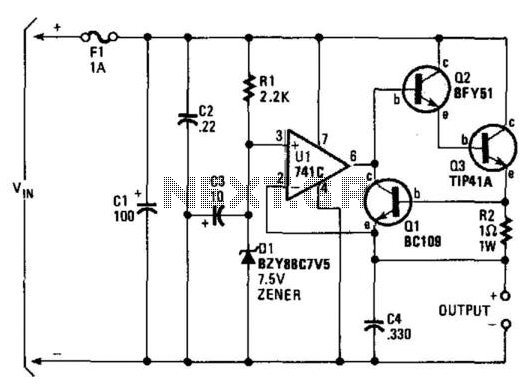
A regulator enables the powering of a 7.5-V cassette recorder or other devices from a 12-V DC automotive system. The circuit can provide approximately 600 mA of current. Q3 requires a heatsink due to its potential to dissipate up...
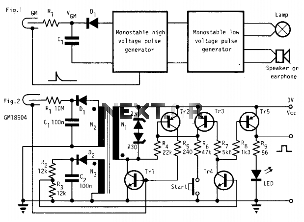
In the absence of radiation, no current is drawn. At normal background radiation levels, the power consumption is extremely low. The instrument may be left on for several months without changing batteries. In this way, the detector is always...
The circuit diagram was designed to create a power supply without utilizing any transformer circuit. This circuit illustrates the advantages as well as the limitations of transformerless power supplies. The transformerless power supply circuit typically employs a capacitive dropper method...
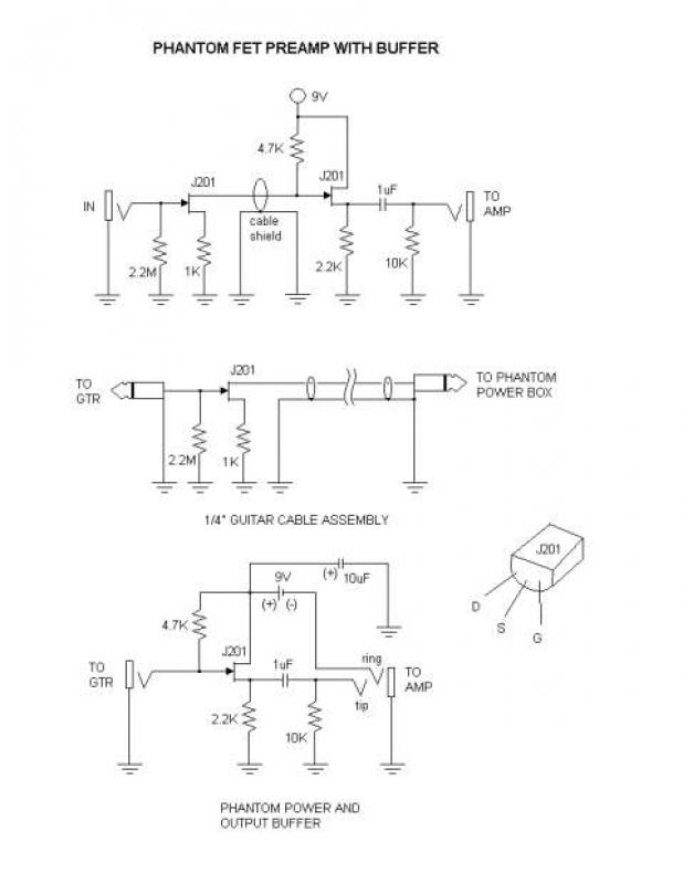
This is a phantom-powered FET preamplifier integrated into a 1/4" guitar cable, similar to the design found on the Tillman site. The amplifier consists of only a few components, making it challenging to trim and solder the leads to...
The following circuit illustrates a battery-powered burglar alarm sensor circuit. Features include foil tape and passive infrared sensors (PIRs), as well as magnetic reed contacts. This battery-powered burglar alarm sensor circuit is designed to provide an effective security solution for...

CO2 gas shielded arc welding power supply electromagnetic vibration circuit is commonly used in farm machinery repair. The maximum arc voltage is 30V, with a maximum welding current of 300A. The wire feed speed ranges from 0 to 12...