
Motorola Mitrek conversion to repeater or link

The document serves as a foundational guide for individuals aiming to construct high-quality Amateur Radio systems. It emphasizes the importance of a solid understanding of electronic principles and schematic interpretation, which are critical for successful repeater operation. The anticipated construction time of approximately 40 hours highlights the complexity and precision required in such projects.
In terms of technical specifications, the document outlines the modulation techniques and frequency ranges necessary for effective communication. The choice of using logarithmic units such as dBm instead of traditional linear measurements is a significant aspect of modern radio design, as it allows for more straightforward analysis and troubleshooting of signal levels.
Furthermore, the document encourages adherence to established technical practices, including the establishment of benchmarks for system performance evaluation. This structured approach not only enhances the reliability of the Amateur Radio system but also fosters a culture of continuous improvement and knowledge sharing among enthusiasts.
Overall, this document serves as a valuable resource for those committed to advancing their skills in Amateur Radio construction and operation, providing insights into both theoretical concepts and practical applications.This document is written in attempt to include everyone interested in serious construction of a quality product. Its very technical, however, written openly and honestly. It`s designed for Amateur Radio (not commercial) at no cost to obtain and is open for discussing, changes and improvements without notice.
Should you feel qualified you are welco me to deviate from the Author`s design. You need to have a basic electronics background with some repeater building experience. Understanding schematic drawings is required. If you are new at the repeater operation you might want to check out additional technical books relevant to this documentation. Anticipate about 40 hours to construct each radio, especially the first one. No free technical support is available, however, printed documents are available on an occasional bases for a modest cost for P & H.
Several images (pictures) on this document, while on-line are enlargeable simply by clicking on them. This gives you an opportunity to "zoom in" for better details should you need it. Other images are not, being unnecessary large files being stored on the server. Some images on this page show only general practice and may not be the completed product or bear accuracy.
For example, one image shows a jumper for 9. 6v switching with the soldering not completed. Production was paused to take some pictures at the time. This is brought up to clarify the final product may be finished without documentation and may vary from what you see here. Some links (that you click on) within this page open new browsers, while others permit you to hit your "back" button.
Reports from readers can go either way on this method of navigation. This document is best viewed with I. E. 5. 0 or later with your screen set for 1024 x 768 or higher resolution. Apologies; time did not permit building this document to be completely friendly with other browsers such as Firefox, Netscape or Opra. You are permitted to copy, print and distribute this document for non-profit use while keeping the Author credited.
The contact information is on the main page of this web site. Amateur Radio is to develop the art of radio and improving operating practices. This can set a good example for others, including the commercial industry, to what Amateur Radio system(s) are capable of doing to provide public service communications in time of need. This includes the technical side, to produce good operating repeater. To be very clear on this philosophy, we will start with very basic theory. "Two-way" Radio systems send intelligence (voice, data, etc. ) by modulating the originating transmitter and decoding (detecting) this modulation at the far end receiver back to something usable to be understood.
How well this is understood depends greatly on how well the system is set up. Just about anyone can "throw" a system together to make it work, somewhat. SRG design specifications call for a better way as you will see in this documentation. A typical (commercial) system uses the audio portion of 300Hz~3KHz for modulation. This document covering modulation frequency and levels will be somewhat different. Also it calls for good technical management. For one, technician organization and discipline is necessary. Plan on what you want to do for a system design and stick to it. Force yourself to keep good practices. One good practice is to establish level references. Some call these "benchmarks", or "baselines". While old Amateur methods used linear (volts, watts, etc) units of measure, most SRG designs and operations use logarithmic units in "dbm". Once accustomed, it`s easier to see the entire picture this way, when designing a system, checking frequency response, and keeps the guesswork out of troubleshooting a subtle level problem.
More information on this subject can be found by clicking here. References can be expressed in a few acronyms. This is very dry reading, however, you 🔗 External reference
Related Circuits
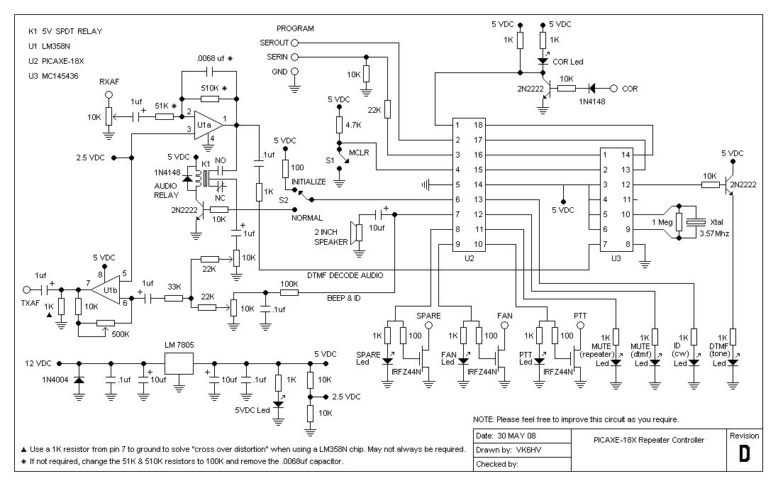
The project involves testing the capabilities of a PICAXE-18X chip operating at 4 MHz for a specific application. It includes designing the circuit, creating printed circuit board (PCB) artwork, etching the PCB, programming the PICAXE in BASIC, and connecting...
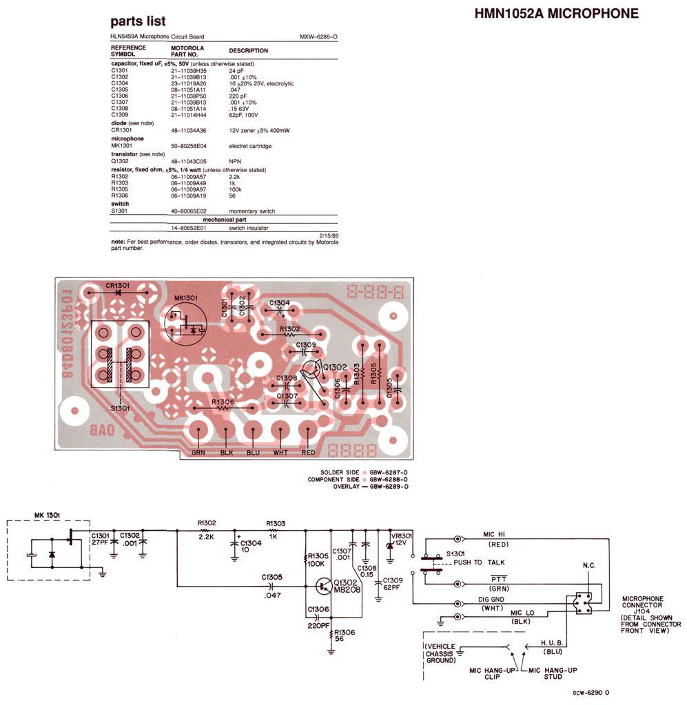
Regardless of the label on the radio or the claims made by the seller, no Spectra radio will function across the entire 136-174 MHz (high band) or 403-512 MHz (UHF) frequency range. Each unit operates within a specific portion...
A basic Infra Red Link for audio communication for distances up to 3 meters. Transistors can be replaced with 2N3904 and 2N2222. In this circuit, Milan has created a basic Infra Red transmitter and receiver. The transmitter comprises a...
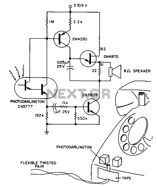
A 2N5777 photo-Darlington cell detects blinking light from transparent plastic buttons. A high-gain 2N3904 transistor is used to switch the power ON and OFF. The circuit can remain continuously connected to a 9 V battery, drawing less than a...
The circuit allows a precision regulated drive current to be set to drive an LED, and in response to a TTL level signal, the LED is switched on and off with rise and fall times of less than 500...
A low-cost continuous wave (CW) superheterodyne receiver operates with a 4.00 MHz intermediate frequency. While there is no automatic gain control (AGC) or RF gain control, the receiver demonstrates good large signal handling capabilities. The design incorporates six bipolar...