
Simple Direct Conversion Receiver

From the 50 ohm receiver antenna jack, first off is a double-tuned band pass filter which was designed by Rick Campbell, KK7B and works very well. The trimmer caps can be the 5 - 20 pF units sold by Digi-key and Mouser. The fixed-value caps in my prototype were inexpensive monolithic ceramic capacitors purchased from Digi-key.
Rick used an NP0 ceramic for the 10 pF coupling cap plus silver-mica type for the 100 pF caps in his original design. For possible lower insertion loss, the probable best/cheapest way would be to use all NPO ceramics for the fixed value caps in this filter.
The RF amp is my favorite popcorn RF amp ; a 50 ohm feedback amp. A grounded-gate JFET amp was tried in its place and was also found to be quite suitable and does not require the -6dB pi attenuator that follows the feedback amp as shown in the schematic. The feedback amp`s 50 ohm input impedance properly terminates the band pass filter. The -6 dB attenuator pad following the amp to helps provide a 50 ohm input impedance for the mixer and to reduce stage gain which aids in preserving the signal to noise ratio of the receiver.
If a builder wants a little more sensitivity, the pi attenuation pad could be reduced to -3 dB however this may effect the receiver dynamic range. The transformer T1 is one of 2 broadband transmission line transformers in this receiver. It transforms the 200 ohm collector impedance to 50 ohms for the succeeding stage. A 50 ohm diode ring mixer (7dBm) such as the Mini Circuits SBL-1 or TUF-1 or homebrew are all suitable.
Following the mixer is an RF diplexer of your choice. The more complex Brifge-Tee ( Q = 1 )diplexer (A) is an excellent design, however maybe overkill in a popcorn superhet such as this. For the (A) diplexer, to get the necessary 800 pF for the capacitors, simply parallel a 470 with a 330 pF or a 120 pF with a 680 pf capacitor.
The inductors at 2. 0 uH are wound on powdered-iron torroids. You can use # 26 AWG wire and it requires 22 turns on a T37-2 core or 20 turns on a T50-2 core. In addition, you can use a #6 material torroid to wind the inductors. This diplexer is described elsewhere on this web site. The simpler (B) diplexer uses a ~3 times the IF frequency that I have seen this basic design in many textbooks and articles and provides reasonable matching with a 50 ohm inductive and capacitive reactance. The cutoff frequency chosen was 11. 78 MHz as this allows the use of a standard value capacitor ( 270pF ). To wind the 0. 68 uH inductor use 13 turns on a T37-2 torroid or 12 turns on a T50-2 powdered iron torroid core. You can easily use 24 - 26 AWG wire for the inductor. Except for the inductors, the IF preamp and IF amp are identical and both warrant a small clip-on heat sink as they draw reasonable current.
The standing current maybe increased or reduced by changing the 47 and 75 ohm resistors connected to the Q2 and Q3 emitter respectively. Factors such as available power supply current versus dynamic range requirements may come into play. One may want to stand more current in the IF preamp and le 🔗 External reference
Related Circuits
The challenge in amplifying weak radio signals lies in the simultaneous amplification of noise. The quality of the received signal is influenced by the level of background noise, which may include man-made interference or static. In this design, the...
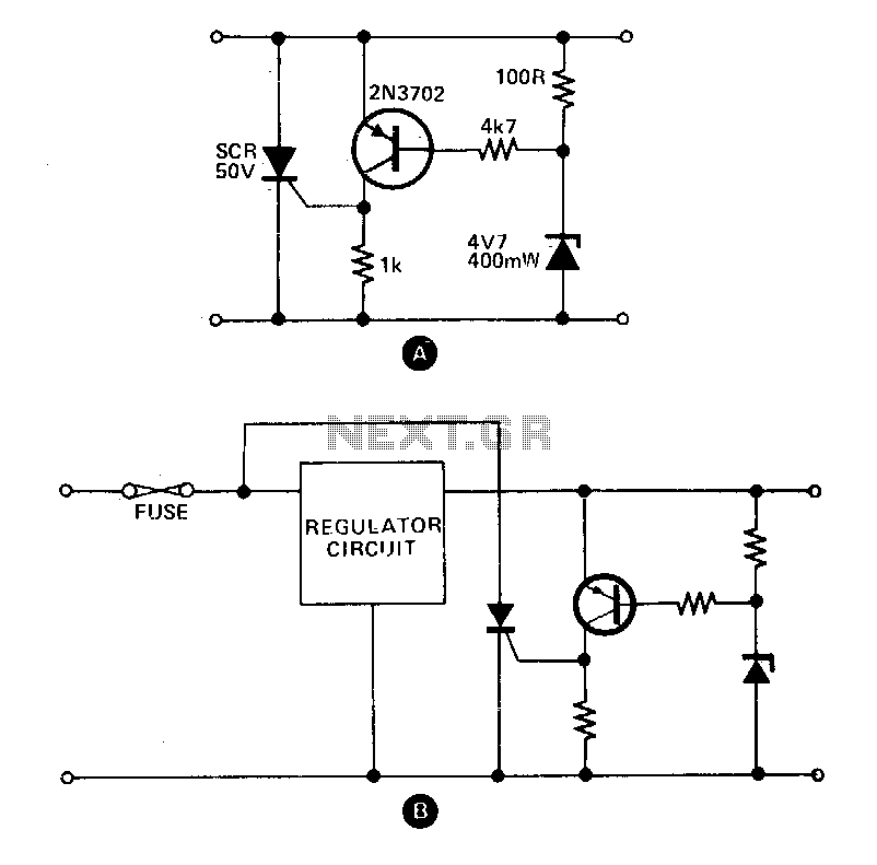
These circuits provide overvoltage protection in the event of a voltage regulator failure or the application of an external voltage. They are designed to be used with a power supply that includes some form of short circuit protection, such...
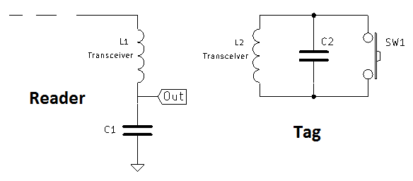
A coil of approximately 1 mH is utilized for both sides of the circuit. Given a chosen frequency of 125 kHz, the required capacitor value is calculated to be 1.62 nF, with a standard value of 1.5 nF selected....

This is a straightforward and easy-to-construct infrared (IR) receiver circuit. The circuit utilizes only a few components and is capable of receiving a 38 kHz carrier signal. The operation of this circuit is simple; whenever the IR LED detects...
Charging current is about 100+mA, which is the internally-limited maximum current of the LP2951. For those wondering, this is compatible with just about any single-cell li-ion battery since li-ion can generally accept a charging current of up to about...
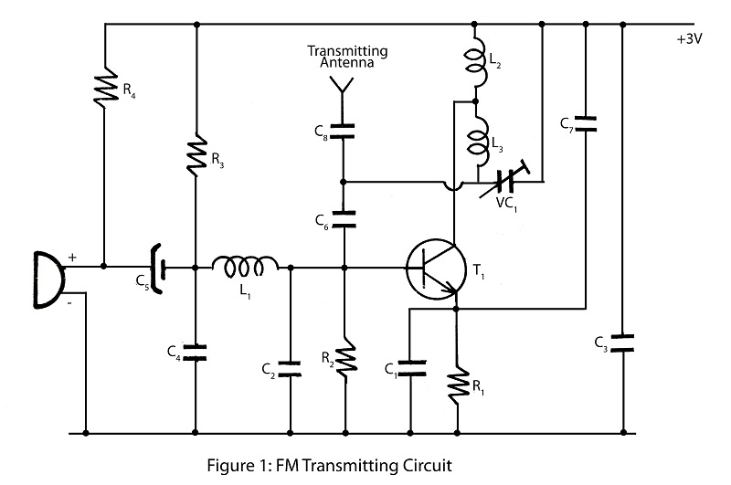
A simple and powerful FM transmitter is an interesting project that utilizes one transistor and operates within a frequency range of 100 MHz. The circuit diagram includes a description of the FM transmitter and various related interesting projects. The FM...