
mouse

The conversion of low-resolution optical encoders from serial mice into high-resolution encoders for telescopes involves several key steps and considerations. The process begins with selecting an appropriate serial mouse, ensuring it features optical encoders rather than potentiometers. The disassembly of the mouse involves careful extraction of the circuit board, preserving the optical components integral to the encoder's function.
Once the encoders are extracted, they must be mounted onto the telescope's axis bearing. The mounting system should be designed to minimize slippage and backlash, which can significantly affect tracking accuracy. The "isolated pressure roller transmission" design allows for controlled pressure application, ensuring that the encoder maintains contact with the bearing surface without excessive force that could lead to wear or inaccuracies.
Calculating the resolution of the encoders is critical for accurate tracking. The DPI value, either obtained from the encoder or calculated through the number of slots and bearing diameter, directly influences the performance of the system. The resolution must be matched to the physical dimensions of the bearing to ensure that the output counts are sufficient for precise movements.
Testing the system involves rotating the telescope's axis and monitoring the output to verify that it corresponds to the expected degrees of rotation. Adjustments to the calculated DPI may be necessary based on the results of these tests to refine the performance further.
In summary, this conversion process requires careful selection of components, precise calculations, and thorough testing to ensure that the resulting high-resolution encoders meet the demands of astronomical applications. With the right approach, serial mouse encoders can provide a reliable and effective solution for digital setting circles in telescopes.This page is for info on converting the low resolution optical encoders, typically found in serial mice, into high resolution encoders needed for DSC`s (Digital Setting Circles), for your telescope, etc. The serial mouse encoders I found had the dpi stamped right in the side of the slotted disk 1, in my case 200 was stamped in the side.
The mouse must be a serial type (like a logitech 3 button mouse), the type that plugs into the serial port. Do not use the common 2 mouse that plugs into the mouse port, they use continuous turn pots, not optical encoders.
The serial mice have a serial interface for the optical encoders already and there isn`t any reason why you couldn`t reuse that portion of the circuit board as well if you needed to interface directly to your computer`s serial port. In my case I discarded that portion when I dissected mine with a jewelers saw as I didn`t need it. The program you use should somewhere ask for the resolution of the encoders and you can calculate an initial setting based on the dpi times the circumference of your bearing surface, if you attach the encoders like I did.
Once you have them working, you test it by rotating the axis through a known number of degrees, preferably a full 360 and watch the readout on your program or digital setting circles to make sure it tracks properly. If there is a difference, simply adjust your final resolution to compensate and then retest. In case the dpi isn`t stamped in the side simply count the number of slots in the disk and multiply by four, then take a micrometer and measure the diameter of the little drive wheel on the encoder shaft and divide the previous calculation by (pi times the dia in inches) and it should give you the dpi.
The result should come very close to a standard dpi. If I were to describe my mounting system, (you can see it is actually very simple), I would call it an "isolated pressure roller transmission" in order that I can use a delicate pressure on the encoder side and a heavier pressure on the axis bearing of the telescope. This way I end up with a zero slippage, zero backlash encoder. It is possible that there is a bit of periodic error, in fact there has to be some, but with the way I use my telescope I do not notice it.
I even have some visable eccentricty in my azimuth bearing and the system still works fine. If you were using the encoders to track with you could factor in any periodic error in an appropriate algorithim anyway, that of course complicates things a little more. The resolution I am getting on my elevation bearing is around 4500 counts as I have a 7 1/4 inch diameter bearing.
My azimuth bearing resolution ends up being over 9000 counts. The bottom line is that serial mouse encoders can work fine if you are careful with your design and use large axis bearings. If you have have either too small of axis bearings or require direct drive encoders this method isn`t going to work too well for you.
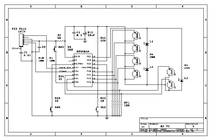
EXAMPLE - For a 200dpi mouse encoder you will need at least a 6 1/2 inch diameter bearing to give the recommended 4000 counts of resolution, ie: for a 400 dpi mouse encoder you only need a 3 1/4 inch diameter bearing. Above are three pictures of a LOGITECH 3 Button mouse Printed Circuit Board very similar to the one I used.
The optical chips and slotted wheels are identical to what I used, however the serial interface IC is different. The best way to dissect the board in this case is to first remove that large rectangular IC, don`t damage the board at this point.
You can clip the leads of the IC if you don`t have specialized tools, and then unsolder the pins individually. Remove all other components except, do not remove the the eight optical chips, the housing that carries the encoder shafts and slotted wheels, and the 120 ohm resistors
🔗 External reference
Related Circuits
Mousebot from Make vol 2 is a fun introduction to robotics. This documentation provides an expanded overview of a Mousey build from start to finish. The Mousebot project serves as an engaging entry point into the world of robotics, particularly...
Power-saving electronic mousetrap. This example describes the minimal power consumption, which only occurs when a mouse enters the control zone during foraging activities. After a 30-second delay, the system enters a wait state, making it suitable for outdoor use....
A mouse operates on two axes: "X" and "Y". When the mouse is moved horizontally, the "X" wheel inside the mouse rotates, and when moved vertically, the "Y" wheel rotates. The movement of the mouse results in the wheels...
This interface design has a long history. It is the first microcontroller design initiated in early 1998, which has evolved over the years. Initially, the schematic diagram for the first prototype was drafted in 1998, and it later became...

While lying in bed and watching movies on a laptop, the idea arose that having a remote control would simplify the tasks of pausing, playing, fast forwarding, rewinding, adjusting volume, and playing the next track without needing to approach...
This circuit utilizes a conventional spring-loaded mouse trap, typically available at hardware stores. When a mouse is caught, the circuit activates and transmits an interrupted tone on the commercial FM band to a nearby radio receiver. It is a...