
electronic mouse trap

This circuit design effectively combines mechanical and electronic systems to create a practical solution for monitoring mouse traps. The use of a Hartley oscillator allows for efficient FM transmission, while the adjustable frequency and tone settings provide flexibility in operation. The ability to monitor multiple traps enhances the functionality of the design, making it suitable for various applications in pest control. The careful consideration of component values, such as the inductance of L1 and the capacitance of C4 and C8, ensures that the circuit operates within the desired frequency range. Additionally, the choice of using a CMOS quad AND gate for generating oscillators is advantageous due to its low power consumption and high noise immunity. The design emphasizes the importance of maintaining proper antenna lengths to ensure effective transmission, which is crucial for reliable operation. Overall, this circuit exemplifies an innovative approach to integrating mechanical triggers with electronic signaling, showcasing the versatility of modern electronic engineering in addressing practical challenges.This circuit uses a conventional spring loaded mouse trap, available from hardware stores. However when a mouse is caught, the circuit triggers and transmits an interrupted tone on the commercial FM band to a nearby radio receiver. This circuit is a small battery powered transmitter which is activated by vibration from a mechanical mouse trap.
Thi s can be done using a microswitchpositioned so that the circuit is off (not transmitting). When the mouse trap is triggered the microswitch lever is moved and activates the transmitter. The transmitter is a standard hartley oscillator, designed to transmit across the FM band approximately, 87 to 108MHz. The transmit frequency is adjustableby means of trimmer C8. The combined capacitance of C4 plus C8 and L1 set the resonant frequency. IC1 is a CMOS quad 2 input AND gate. Gates U1a and U1b create a square wave astable oscillator ofabout 2Hz. The output of gate 1b is wired tothe input of gate 1c. Similarly gates 1c and 1d form another astable oscillator, this time about 2kHz. The 2kHz oscillator is activated only whengate 1b is high, all gates forming and interrupted oscillator.
The tone of this oscillator is adjustable via the preset R2. The output of the oscillator now directly drives the transmitter comprised of Q1 and associated components. The transmitter will be on when the output fromgate 1c is high and off when gate 1c is low. As the input signal is a sqaure wave, there will be some cross modulation and the transmitter signal willbe heard at more than one point across the FM band.
As the output power is limited, this is not really a problem and with just 5 inches of wire as anantenna, I could hear the transmitter with an ordinary radio 15 metres away. The antenna is connector to Q1 collwctor and will work with just a fewinches of wire. A telescopic whip may be used instead. Do not use lengths of wire longer than 30 inches as these will detune the oscillator andthe circuit may not transmit at all.
L1 is 7 turns of 20swg wire wound on a 6 mm drill bit. This forms an inductor of approximately 150 nH. The value of the inductance can be alteredby compressing or expanding the turns. Hold one end of the wire against the drill bit and start to wind the turns clockwise. Continue until all 7 turns have been completed, and the coil looks like the image of the right hand side. Trim any excess wire so both ends are same length and scrape about 3mm of insulationoff the opposite end.
An added feature is that multiple mouse traps can be monitored. Simply build more identical circuits and tune them to the same transmitting (RF) frequency. R2 must be set different in each case so that a different note is heard for each mouse trap. If two traps activate simultaneously then a "beat" note willbe heard which will be the sum of two different notes. Finally a picture of my prototype on breadboard. Breadboard and veroboard have adjacent track capacitances of around 0. 2pF. This may not soundmuch but limits the high frequency response of any circuit. Although construction on veroboard is possible either a PCB layout or copper cladboard and copper island construction preferred.
🔗 External reference
Related Circuits
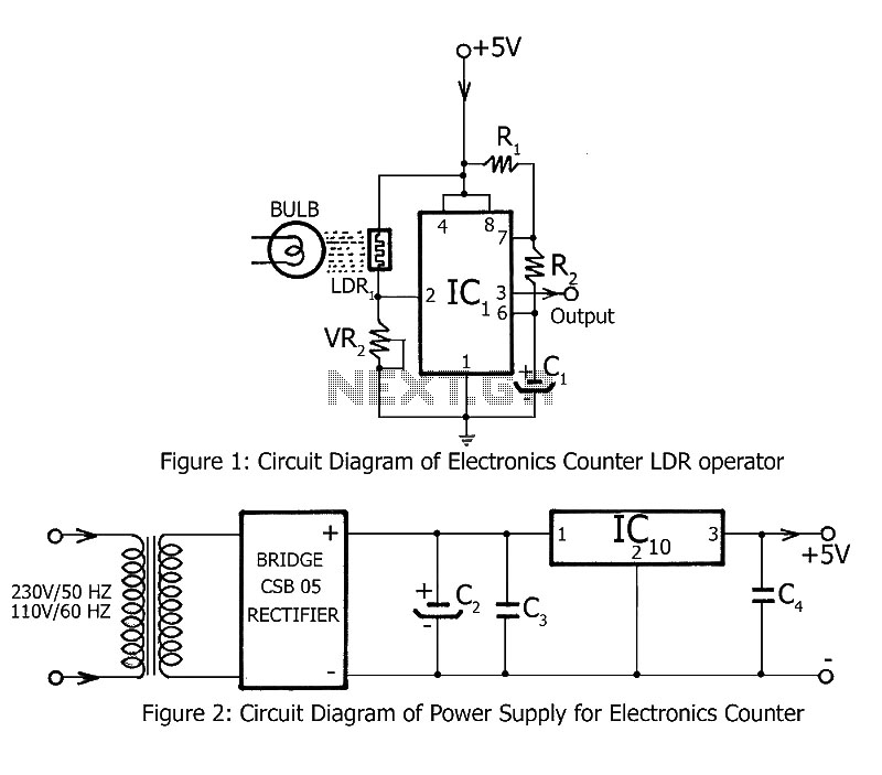
Simple counting can be performed by anyone, but counting over large intervals can be tedious and prone to errors. A previously published project, the Digital Counter, serves as a foundation for this electronics counter, which is the second project...
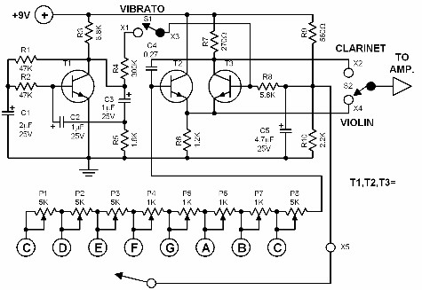
This electronic organ is simple to construct and can provide hours of enjoyment, particularly for children. The circuit is fundamentally an emitter-coupled oscillator consisting of transistors T2 and T3. A square wave voltage can be sampled from the collector...
To put the relay in tension the 4 buttons S1 S4 must be pressed. If anyone of the 4 buttons S5 S8 are pushed the relay doesn't tension (doesn't receive supply voltage). The supply voltage must be equal to...
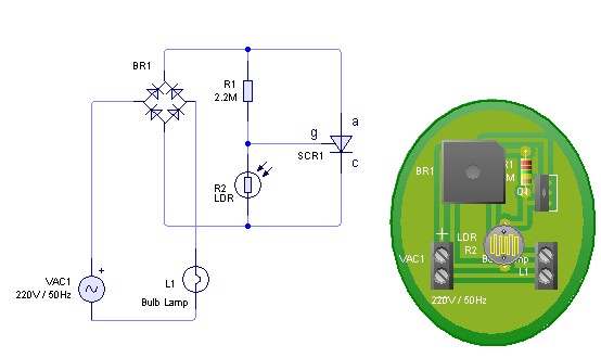
Adjust the value of R1 to achieve optimal performance of the LDR sensor. If, in practice, a resistance of 2.2 MΩ still activates the lamp, it is possible to increase the value of R1 to a larger resistance of...

A keyboard key functions by establishing an electrical contact between the surface of the keyboard and the underlying circuit when the keytop area is pressed. This mechanism was utilized by some home computers in the early 1980s and has...

This is an integrated electronic mailbox circuit diagram designed for a front door. It activates when the door is opened. Additionally, when the cabinet photo detector is exposed to light, it will... The integrated electronic mailbox circuit is designed to...