
MPF102 FET Preamplifier
The circuit design incorporates a single JFET configuration aimed at achieving a specific gain level suitable for applications such as guitar amplifiers. The addition of a source resistor bypass capacitor is crucial for enhancing gain, enabling the circuit to mimic the characteristics of traditional tube preamps. The removal of the 220K output resistor and the introduction of a secondary amplification stage is recommended for improved performance.
The power supply for the JFET preamplifier must be carefully considered to avoid damaging components. A low-voltage, ripple-free supply is essential, with options including a filament supply with a voltage doubler circuit or a battery for portable applications. The choice of JFETs, such as the MPF102, while feasible, presents limitations in output volume, necessitating careful consideration of circuit design to ensure adequate performance.
In scenarios where a higher output power is desired, the circuit can be adapted to utilize higher voltage supplies, although the limitations of the selected JFET must be acknowledged. The proposal to replace tube circuits with JFETs introduces uncertainty regarding equivalency, necessitating empirical testing and potential circuit modifications.
The design also includes a tremolo oscillator, which requires careful integration to ensure functionality. The mixing of signals at specific gate resistors is a critical aspect of the design, and caution is advised in implementing this feature to avoid complications in circuit operation.
For more robust applications, transitioning to a two-FET configuration using high-voltage MOSFETs like the LND150 and DN2540 presents a viable alternative. These components allow for higher power outputs while maintaining operational integrity at lower voltage levels. Proper handling and circuit design are imperative to prevent oscillations and ensure reliable performance.The circuit that I`ve described is a one-JFET design without much gain. You can significantly boost the gain by adding a source resistor bypass capacitor. The result would be something like one stage of the original tube preamp in a guitar amplifier. Next, you`d eliminate the 220K resistor on the output and couple in another stage. You`d also have to invent a new power supply for your JFET preamplifier. Whatever you do, don`t hitch up the tube power supply. It will spread JFET fragments all over the room. And probably all across the state. Instead, you need a good, ripple-free, low-voltage supply. Maybe you can use the filament supply with a doubler circuit and filter. Or in a pinch, you can even use a battery. I`m not sure exactly how well the JFET version would work. JFETs can sound very fine, but I`ve never seen a tube-to-JFET sub book. What you propose to do is to replace one design with another. Nobody can say for sure if the new design is equivalent in every way. You`d have to try it, tweak it, and see how you like it. Fortunately, you can temporarily patch in a JFET amp. Remove the tubes. Disconnect the final coupling capacitor, isolating the old tube circuit. Set the JFET breadboard atop the tube chassis. (You can bolt your circuit down later. ) Capacitively couple the JFET preamp to the tube power amp. A few alligator clips would do the job. I mentioned battery operation. Some will want to operate the preamp on a nine-volt transistor battery. Nine-volt operation requires circuit changes. Here`s a nine-volt version of my preamp. ANSWER. An MPF102 would work as the power amp. It really isn`t an acceptable power device, though. Your speaker volume wouldn`t be very loud. The output volume will be comparable to what you get from a transistor radio. (At best. ) What you propose is somewhat like substituting a 12AU7 tube for a 6BQ5 power output tube. I doubt that anyone would do that. Yet maybe an earphone amp would use such a low-power design. The rest of this answer follows through on a hypothetical, low-power JFET circuit. The provided schematic isn`t practical. It also depends on the preamplifier from an earlier question. On the drawing`s left side is Q3, a tremolo oscillator. On the right side is Q4, the JFET power amplifier. Half the tremolo signal mixes with the full input signal at gate resistors R7 and R8. ™Caution. The Q3 tremolo oscillator (right) isn`t a stomp box. Using this phase-shift oscillator in a stomp box requires designing a simple modulator circuit. If you can`t do that, don`t build this circuit. Also: The Q4 circuit isn`t a practical amplifier. ANSWER. Well, we`re moving pretty far away from preamplifier topics. One way to boost output power is to increase the power (B+) voltage. Now we`re not talking about a battery amplifier anymore. For example, you might use 30, 50 or even 100 volts. Of course, the MPF102 JFET tops out at 25 volts. You`ll have to change devices. I don`t recommend using it at over 20 volts. Let`s consider a two-FET rig. This time, our model is the venerable Fender Champ Model 5C1. We`ll use high-voltage MOSFETs instead of JFETs. The preamplifier is an LND150 and the power amplifier is a DN2540. Supertex makes both parts. You can order them inexpensively from Mouser. I`m still thinking about this amplifier, so let`s save the details for later. The power limit for the LND150 is 500 volts. The limit for the DN2540 is 400 volts. Using them at a lesser voltage, such as 50 volts, is just fine. In fact, the curves indicate that a voltage of 100 or lower would be wise. Above 100 volts, the current-handling ability of these devices drops off. If you plan to build such an amplifier, take care! The LND150 and DN2540 can handle swings up to 20 volts peak to peak. But no more. Also, MOSFETs sometimes oscillate at VHF frequencies. This oscillation can be destructive. Elsewhere on the Web, I see that people are supressing the oscillat 🔗 External reference
Related Circuits
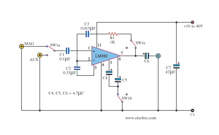
This is a simple preamplifier circuit. It can accept a general AUX sound signal as well as a signal from a microphone. The purpose of the circuit is to amplify the sound signal at the initial stage using an...
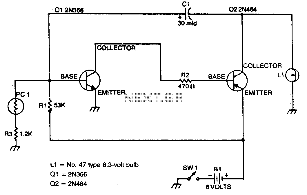
This flasher activates only during nighttime, providing bright illumination and automatically turning off when sunlight is detected. The photocell should be positioned on top of the unit to maximize light detection. The circuit for the nighttime flasher utilizes a photocell...
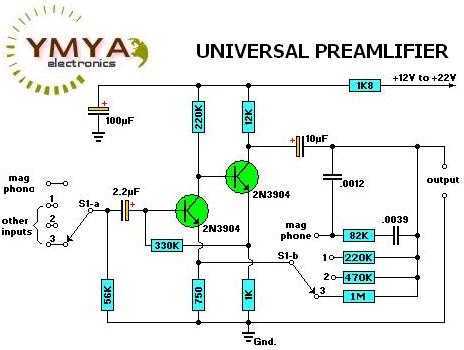
Most audio amplifier systems must have preamplifiers with many different characteristics. These include high-gain linear response for magnetic microphones, low-gain linear response for tuners, and high-gain RIAA equalization for magnetic phone cartridges. To meet this broad requirement, most amplifier...
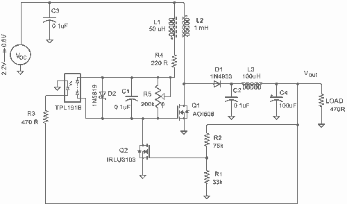
It employs a low threshold MOSFET and two coupled coils to function as a joule thief. An additional MOSFET is utilized for regulation. The circuit operates as a joule thief, which is a type of DC-DC converter designed to extract...
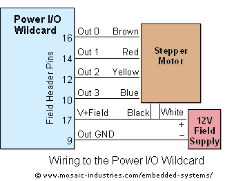
For optimal efficiency, set MAX_STEPPERS to the number of stepper motors being controlled, with a maximum limit of four. Motors are identified by indices 0, 1, 2, and 3. On the QCard, there is a trade-off between the number...
This circuit falls under the category of an astable multivibrator. It is designed to test N-channel MOSFETs, specifically power types such as the IRF830, to determine their functionality. The astable multivibrator circuit is a type of oscillator that continuously switches...