
Mosfet Tester

The astable multivibrator circuit is a type of oscillator that continuously switches between its high and low states without requiring any external triggering. This makes it particularly useful for applications like testing MOSFETs, where a square wave signal is needed to effectively drive the gate of the device under test.
The circuit typically consists of two resistors (R1 and R2) and a capacitor (C1) connected to an N-channel MOSFET. The resistors are used to set the charging and discharging times of the capacitor, which in turn determines the frequency of the oscillation. The output can be taken from the drain of the MOSFET, which will produce a square wave signal.
When testing an N-channel MOSFET such as the IRF830, the gate of the MOSFET is connected to the output of the astable multivibrator. The square wave signal will turn the MOSFET on and off rapidly. By observing the output at the drain, one can assess whether the MOSFET is functioning properly. If the MOSFET turns on and off in response to the square wave signal, it indicates that the device is operational.
The values of the resistors and capacitor can be adjusted to change the frequency of the output signal, allowing for testing across different operational conditions. Proper selection of these components is crucial for ensuring that the MOSFET is driven adequately within its specified gate threshold voltage range.
This astable multivibrator circuit serves as a simple yet effective means for evaluating the performance of power MOSFETs, providing a visual indication of their operational status through the generated square wave output.This circuit included in the category astable multivibrator. This circuit is used to test? N-Mosfets (the power kind e.g irf830), whether it works or not. If. 🔗 External reference
Related Circuits
A simple device designed for quickly checking common infrared remote controls can be beneficial for electronics enthusiasts who often need to repair or test these widespread devices. A reliable circuit was created using a few components: the LED will...
High Quality simple design No need for a preamplifier Can be directly connected to CD players, tuners and tape recorders. Simply add a 10K Log potentiometer (dual gang for stereo) and a switch to cope with the various sources...
A photodiode, SFH2030, serves as an infrared sensor. A MOSFET operational amplifier, CA3140, is utilized in differential mode to amplify the current pulses from the photodiode. LED1, an ordinary colored LED, illuminates when infrared radiation is detected. The output...
This headphone buffer is based on Greg Szekeres' MOSFET Headphone Driver. It is a robust and reliable zero feedback, class A circuit. The power supply is choke regulated. The circuit is configured for low impedance headphones like my 32-ohm...
The following segment provides the enhanced Motorola schematic for a typical application of the MRF141G, which includes parasitic stabilization features. The MRF141G is a broadband power RF MOSFET capable of delivering a conservatively rated 300 watts across the FM...
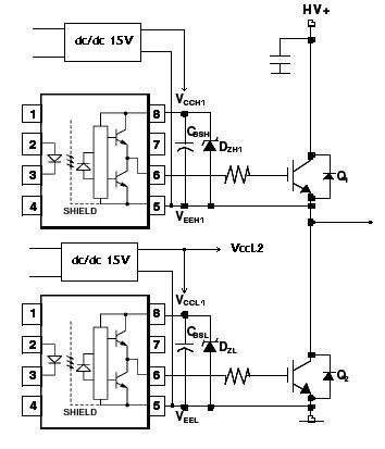
An H-bridge circuit has been developed utilizing four floating gate drivers and four insulated gate bipolar transistors (IGBTs). The attached schematic illustrates one half of the H-bridge configuration. The circuit operates effectively, but there are additional considerations to address. The...