
Automatic safety flasher

The circuit for the nighttime flasher utilizes a photocell sensor to control the operation of the light source. The photocell, also known as a light-dependent resistor (LDR), plays a critical role in the functionality of the device. When ambient light levels fall below a certain threshold, the resistance of the LDR decreases, allowing current to flow through the circuit and activating the flasher.
The circuit typically consists of a power supply, the photocell, a relay or transistor for switching, and the light source, which may be an LED or incandescent bulb. The photocell is connected in series with a resistor to form a voltage divider. As the light level decreases at dusk, the voltage across the photocell and resistor changes, triggering the relay or transistor to close the circuit and turn on the light.
To prevent the light from turning on during the day, the photocell must be mounted in a location that receives maximum exposure to sunlight. This ensures reliable operation and prevents unnecessary power consumption during daylight hours. The relay or transistor used in the circuit should be rated for the current and voltage of the light source to ensure safe and effective operation.
Additionally, a delay circuit may be incorporated to prevent flickering during twilight hours when light levels fluctuate. This can be achieved using a simple RC (resistor-capacitor) timing circuit that introduces a short delay before the light turns off after sunrise.
Overall, this schematic design emphasizes efficiency and reliability, ensuring that the flasher operates as intended while providing optimal illumination during the night.This flasher only comes on at night. It furnishes a bright nighttime illumination, and shuts itself off automatically as soon as the sun comes up The photocell must be mounted on top of the unit in such a way as to detect the greatest amount of available light.
Related Circuits
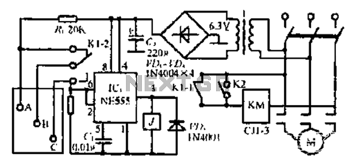
After the 3.40V power supply, the voltage is reduced to 6.3V through a full transition rectification using VDi and V sulfone. The C1 filter provides voltage stabilization after the caution circuit operates at the NE555 voltage level. When the...

This simple automatic emergency light has advantages over conventional emergency lights: the charging circuit stops automatically when the battery is fully charged. This automatic emergency light features a straightforward design that enhances its operational efficiency compared to traditional emergency lighting...
A large mirror is installed on the left wall, enhancing the brightness of the room. However, when watching movies, a dark environment is preferred, as reflections of the film appear in the mirror, which can be distracting. To address...
This document does not aim to provide an extensive account of the integrated circuits (ICs) used in this circuit. For additional information on this topic, please refer to the "Flip-Flop Made With A LM556 Timer Chip" section and the...
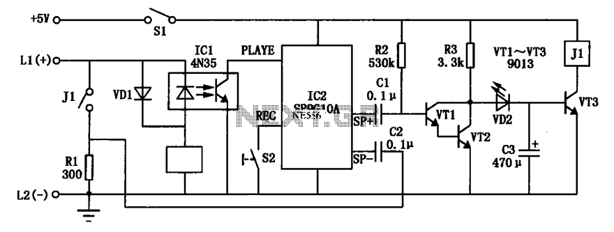
An automatic telephone responder circuit is illustrated. It incorporates a 10-second voice recording circuit (SR9G10A) activated by the power switch (S2). The circuit utilizes an electret microphone (IC2) for sound input. To initiate the response, the user must press...
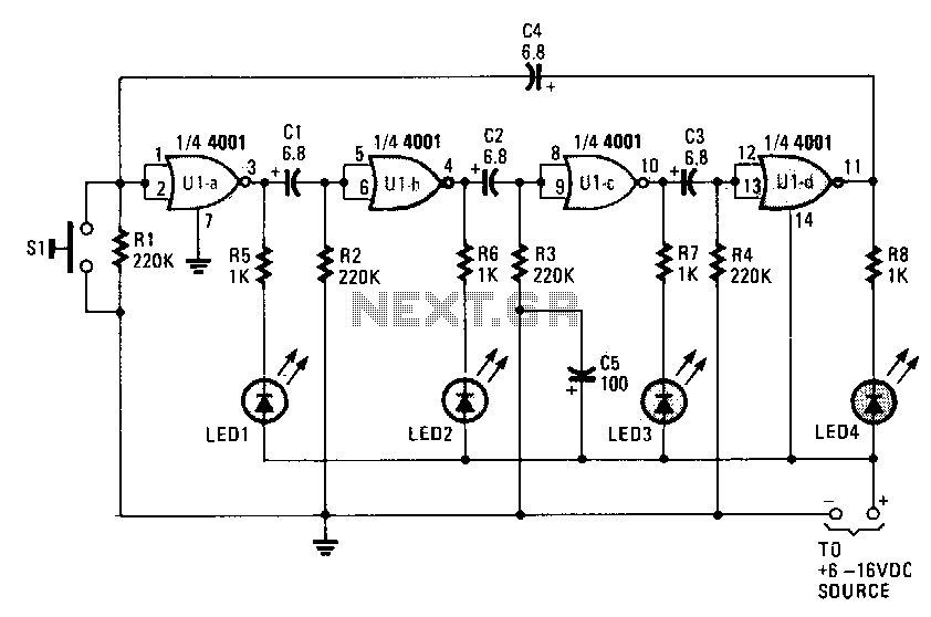
When power is initially applied, two of the LEDs illuminate while the other two remain off until the timing cycle reverses. The LEDs flash in pairs; however, by pressing and holding switch S1 until only one LED is lit,...