
Photo Light with Relay

The described circuit utilizes a CMOS dual D flip-flop (CD4013) to create a toggle mechanism for controlling a relay or similar load via a momentary push button. The CD4013 consists of two independent D-type flip-flops, which can be configured to change their output state on the rising or falling edge of the clock signal generated by the push button.
When the push button is pressed, it sends a clock pulse to the flip-flop, causing it to toggle its output state. This output can then be used to activate a relay. The relay should be a double pole, double throw (DPDT) type to allow for versatile control of the load. The DPDT relay can switch both the load and provide feedback to the circuit, ensuring that the flip-flop maintains its state until the next button press.
To implement this, a single NPN transistor can be used to drive the relay coil. The transistor is controlled by the output of the flip-flop, allowing the relay to be energized or de-energized based on the state of the flip-flop. The relay contacts can be wired such that one set is used to control the load, while the other set can be used for feedback to the flip-flop, ensuring that the circuit behaves as intended.
For multiple control points, several push buttons can be connected in parallel to the clock input of the flip-flop. This configuration allows the relay to be toggled from different locations without the need for complex wiring or additional components. The circuit design provides a simple yet effective solution for remote control applications where momentary push button activation is required.
Additional considerations include debouncing the push button to prevent multiple toggles from a single press, which can be achieved using a capacitor and resistor in conjunction with the push button. Proper power supply decoupling and protection for the relay and transistor are also essential to ensure reliable operation.The circuit below uses a CMOS dual D flip flop (CD4013) to toggle a relay or other load with a momentary push button. Several push buttons can be wired in parallel to control the relay from multiple locations. The circuit below requires a double pole, double throw relay in conjunction with a single transistor to allow toggling the relay with a momentary push button. One set of relay contacts is used to control the load, while the other is used to provide feedb 🔗 External reference
Related Circuits
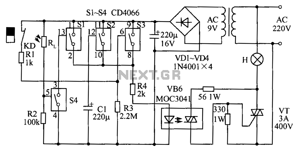
The circuit diagram illustrates a group of four analog electronic circuit switches (S1 to S4). Switches S1, S2, and S3 are utilized in a parallel delay circuit. When the power is activated, resistor R4 drives the triac VT, which...
The circuit was originally available in kit form from a surplus supplier, but it is likely more widely accessible now. It introduces innovative concepts such as utilizing a 555 timer as a pulse width modulator (PWM) and employing serial/parallel...
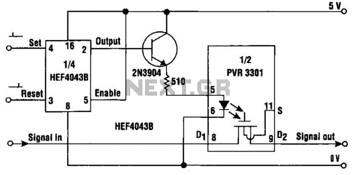
This simple circuit provides a solid-state equivalent of the electromechanical latching relay. The switching mechanism is clean, highly resistant to vibration and shock, and is not sensitive to magnetic fields or position. The circuit operates as follows: a set...
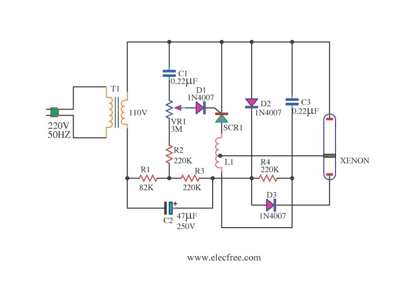
This is a Xenon Strobe Light circuit that utilizes a Xenon tube to produce various brightness levels. The blinking speed can be finely adjusted to be fast or slow using VR1. The circuit incorporates a Silicon Controlled Rectifier (SCR). The...
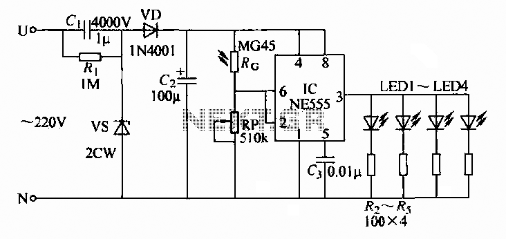
A 220V AC input is converted to a DC operating voltage of approximately 3.3V using a capacitive G buck regulator, a rectifier diode (VD), and a filter capacitor connected to an NE555 integrated circuit (IC). The IC functions as...
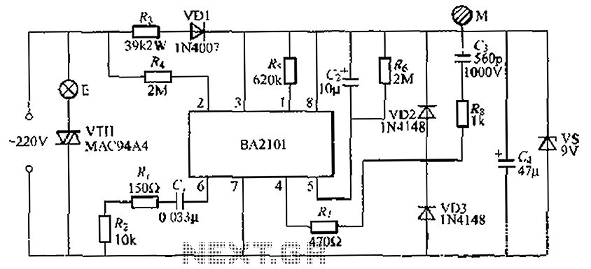
The BA2101 is a dimming controller utilizing an ASIC to create a barrel of light touch stepping. It is a non-constant lamp suitable for heir light. Each touch on the electrode sheet M can adjust the lamp brightness through...