
Multi Switch Controlled Relay

The Multi Switch Controlled Relay circuit operates by allowing multiple switches to control a single relay, thus enabling the activation or deactivation of home appliances from different locations. The circuit typically includes a relay, which acts as an electromechanical switch, and one or more control switches that can be positioned strategically throughout the home.
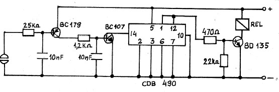
The core component of this circuit is an integrated circuit (IC) designed for control purposes. This IC can handle multiple input signals from the switches and use them to drive the relay. When a switch is activated, the IC processes the signal and energizes the relay coil, closing the relay contacts and allowing current to flow to the connected appliance.
The schematic diagram for this circuit will typically depict the IC, the relay, and the switches. The IC may include additional components such as resistors, capacitors, and diodes for signal conditioning and protection. For example, a diode may be placed in parallel with the relay coil to prevent back EMF from damaging the IC when the relay is turned off.
In practical applications, this circuit can be used to control lights, fans, or any other electrical appliance, providing convenience and flexibility for users. The ability to control an appliance from multiple locations enhances user experience and can improve energy efficiency.
Overall, the Multi Switch Controlled Relay circuit represents a versatile solution for home automation, leveraging a simple yet effective design to enhance control over household devices.Multi Switch Controlled Relay circuit is used to control home appliance circuit diagram with description of multi switch controlled relay utilization 1 IC various control IC. 🔗 External reference
Related Circuits
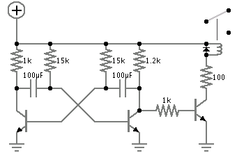
The circuit below requires a double pole, double throw relay in conjunction with a single transistor to allow toggling the relay with a momentary push button. One set of relay contacts is used to control the load, while the...

Typically, home appliances are controlled using switches, sensors, and similar devices. However, physical contact with switches can pose risks, especially in the event of a short circuit. The circuit outlined here eliminates the need for physical contact to operate...
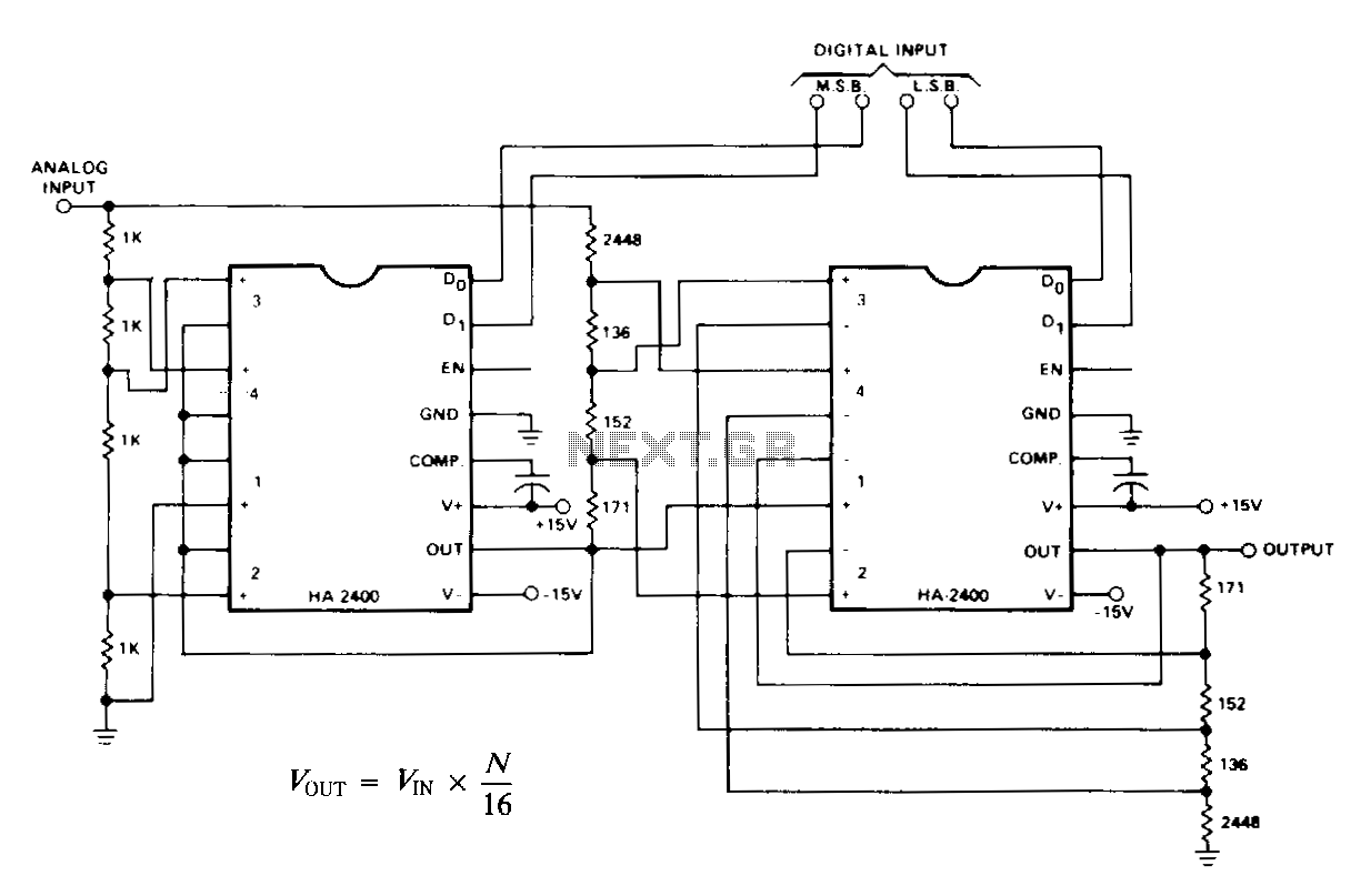
N represents a binary number ranging from 0 to 15, generated by the digital input. When the analog input is set to a fixed DC reference, the circuit functions as a standard 4-bit digital-to-analog converter (DAC), producing an output...
Powering this circuit with a 6V alkaline battery operates effectively with 100µF capacitors. However, there is an issue when attempting to replace the LED with a DPDT relay; a 6V relay previously available does not activate. Additionally, when using...
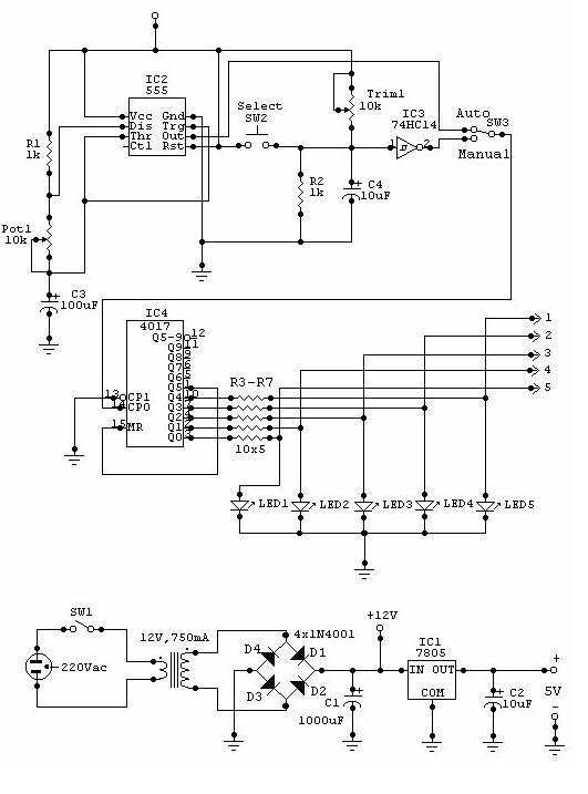
This circuit can be utilized for multiple cameras with a single monitor. The operation can be manual or automatic. In automatic mode, the switch... This circuit is designed to enable the connection of multiple cameras to a single monitor, allowing...
A collection of touch switch circuits is presented. A touch switch is an electronic device that allows control of a circuit simply by touching a sensor. The circuit diagram illustrates a simple design that utilizes only eight components. The...