
Wireless On-Off Switch

This infrared-based control circuit is an innovative solution for managing home appliances without direct contact, enhancing safety and convenience. The use of an infrared LED and phototransistor combination provides a non-invasive means of activation that significantly reduces the risk of electrical hazards associated with traditional switch-based systems. The CA3140 operational amplifier serves as the core component for signal amplification, ensuring that even minimal interruptions in the infrared beam can effectively trigger the control mechanism.
The design's sensitivity can be fine-tuned through the voltage-divider preset, allowing for customization based on the specific requirements of the application or the environment in which the circuit operates. This feature makes the circuit adaptable for various scenarios, whether in residential settings or commercial applications where hygiene and safety are paramount.
The relay (RL1) acts as a switch that can handle higher loads, making it suitable for controlling various appliances, including those that require significant power, such as hand dryers or automatic flush systems. The low current consumption of the circuit also contributes to energy efficiency, making it an environmentally friendly option for modern homes.
In terms of assembly, careful attention should be paid to the layout on the PCB to minimize interference and ensure reliable operation. Proper identification of components and verification of connections is crucial to prevent malfunctions. Overall, this circuit exemplifies a modern approach to appliance control, combining safety, efficiency, and ease of use in a compact design.Normally home appliances are controlled by means of switches, sensors, etc. However, physical contact with switches may be dangerous if there is any shorting. The circuit described here requires no physical contact for operating the appliance. You just need to move your hand between the infrared LED (D2) and the phototransistor (Q1). The infrared rays transmitted by D2 is detected by the phototransistor to activate the hidden lock, flush system, hand dryer or else. This circuit is very stable and sensitive compared to other AC appliance control circuits. It is simple, compact and cheap. Current consumption is low in milliamperes. The circuit is built around an IC CA3140, D2, phototransistor and other discrete components. When regulated 5V is connected to the circuit, D2 emits infrared rays, which are received by phototransistor Q1 if it is properly aligned.
The collector of Q1 is connected to non-inverting pin 3 of IC1. Inverting pin 2 of IC1 is connected to voltage-divider preset R4. Using preset R4 you can vary the reference voltage at pin 2, which also affects sensitivity of the phototransistor. Op-amp IC1 amplifies the signal received from the phototransistor. Resistor R3 controls the base current of transistor BC548 (Q2). The high output of IC1 at pin 6 drives transistor Q2 to energies relay RL1 and switch on the appliance, say, hand dryer, through the relay contacts.
The working of the circuit is simple. In order to switch on the appliance, you simply interrupt the infrared rays falling on the phototransistor through your hand. During the interruption, the appliance remains on through the relay. When you remove your hand from the infrared beam, the appliance turns off through the relay. Assemble the circuit on any general-purpose PCB. Identify the resistors through colour coding or using the multimeter. Check the polarity and pin configuration of the IC and mount it using base. After soldering the circuit, connect +5V supply to the circuit. 🔗 External reference
Related Circuits
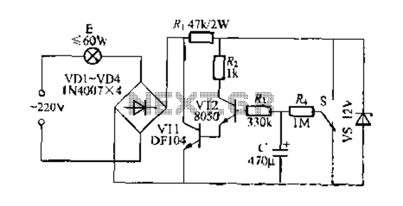
This circuit is a gradual clear/fade switch for a two-wire connection, designed for simple installation. It activates the lights as needed by turning the switch dial upward. A positive supply of 2V is provided through resistor R. The capacitor...
The integrated circuit input side contains an oscillating circuit, where the oscillation frequency is determined by the external components L1, C1, and the sensor's equivalent capacitance. The equivalent capacitance increases as the sensor is immersed in liquid. The oscillating...
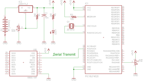
There are two schematics to examine for constructing a transmitter/receiver system. The first schematic is the transmitter, featuring a variable trimpot connected to RA0. The trimpot's value will be transmitted from the Tx pin of the PIC to the...

This is a simple toggle switch that can be operated through sound signals such as a whistle or clap. The output of the toggle remains either low or high until... This circuit utilizes a sound sensor to detect specific audio...
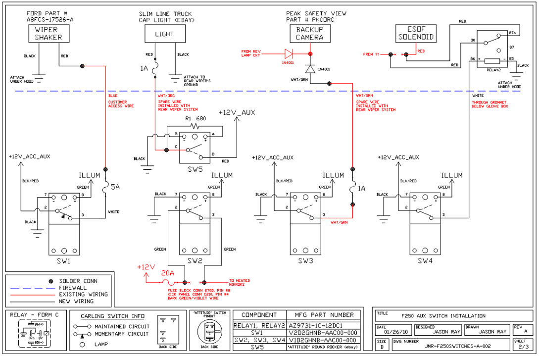
A +12V switched wire was routed back to the camera wiring and connected at the same point as the reverse lights. This configuration allows either the reverse lights or the switch to activate the camera. The critical component in...
This post presents an interesting topic about switching power supply circuit diagrams for those who wish to learn more. A switching power supply is a type of power supply that uses a switching regulator to convert electrical power efficiently. Unlike...