MultiKey - One Wire Keypad

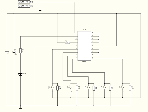
This project can be utilized for various purposes, with one of the most common applications being the interfacing of a keypad for electronic projects. While several pre-made keypads are available on the market, they typically operate with matrix connections, requiring seven pins for a 12-button configuration. For novice programmers, programming matrix keypads can be somewhat challenging. The circuit described here can accommodate between 4 to 12 push buttons using only a single wire connection (in addition to a ground pin), enabling the use of a compact microcontroller, such as an 8-pin variant, to manage the keypad. Additionally, it features a setup mode that allows for the adjustment of the key output rate, which is stored in the microcontroller's memory. It is important to note that pins 11, 12, 13, 15, 16, 17, and 18 are connected to ground. To add more buttons, simply disconnect the ground connection for each additional button, connect the pin to a push button, and include a resistor in the same manner as with the initial buttons.
This circuit design presents a simplified method for integrating a keypad into electronic projects, particularly beneficial for users with limited programming experience. The use of a single-wire connection significantly reduces the pin count required on the microcontroller, allowing for more efficient use of available resources.
The circuit operates by utilizing a resistor ladder or a similar method to differentiate between the button presses. Each button is connected to a unique resistor value, which creates a unique voltage at the input pin of the microcontroller when a button is pressed. This voltage can be read by the microcontroller's analog-to-digital converter (ADC), enabling it to determine which button has been activated based on the corresponding voltage level.
The setup mode is particularly advantageous, as it allows users to customize the responsiveness of the keypad to suit their specific application needs. The ability to save settings in the microcontroller's memory ensures that configurations are retained even after power is cycled, enhancing the overall user experience.
In terms of hardware implementation, the circuit requires a microcontroller with an ADC, several push buttons, and resistors for voltage division. The connections should be made carefully, ensuring that the ground pins are correctly assigned to avoid short circuits. The layout should also consider the physical arrangement of the buttons for ease of use.
Overall, this keypad interface circuit provides a flexible and user-friendly solution for integrating input devices into electronic projects, making it an excellent choice for hobbyists and professionals alike.This project can be used for many different purposes. Probably the most used application would be to interface to any electronic project that requires a keypad. There are several ready made keypads on the market, but those work with matrix connections and require 7 pins for a 12 button pad.
For new programmers, matrix keypads can be a bit tricky t o program. My circuit can use from 4 up to 12 push buttons with only one wire connection ( plus ground pin ) making possible to use a small microcontroller like an 8 pin to use this keypad. It`s also built in a setup mode where it`s possible to change the key output rate. This setting is saved in the microcontroller`s memory. Notice that pins 11, 12, 13, 15, 16, 17 and 18 are connected to ground. For each button added just remove the ground connection and connect the pin to a push button and add the resistor the same way as the first buttons.
🔗 External reference


