
Multiple feedback low pass filter

To achieve a low frequency cutoff at 10 Hz while maintaining a voltage gain (AVCL) of 4, a circuit can be designed utilizing operational amplifiers (op-amps) configured in a non-inverting amplifier setup. The low bias currents of the op-amps are essential, as they allow for the use of high resistance values in the feedback network, which in turn minimizes the loading effect on the input signal. This design choice is crucial for applications requiring high input impedance and low output impedance.
The cutoff frequency (fc) is determined by the RC time constant of the circuit, where R represents the resistance and C represents the capacitance. The formula for the cutoff frequency is given by:
fc = 1 / (2πRC)
To achieve a cutoff frequency of 10 Hz, careful selection of R and C values is necessary. For instance, using a resistor of 15.9 kΩ in conjunction with a capacitor of 1 µF would yield a cutoff frequency close to the desired specification.
The passband ripple of 0.1 dB indicates that the circuit should maintain a relatively flat frequency response within the passband, which can be achieved through proper component selection and feedback network design. This ensures that the gain remains consistent across the desired frequency range, enhancing the overall performance of the circuit.
In some configurations, particularly when dealing with high-frequency signals or when stability is a concern, the addition of small capacitors (25-50 pF) may be necessary. These capacitors can help mitigate potential oscillations and improve the phase margin of the circuit, ensuring stable operation across varying conditions. The placement of these capacitors should be strategically considered in the layout to minimize parasitic inductance and capacitance, which could adversely affect the performance of the circuit.
Overall, this configuration is suitable for low-frequency applications where precision and stability are paramount, and the careful selection of components will ensure optimal performance.The low bias currents permit high resistance and low capacitance values to be used to achieve low frequency cutoff. fc = 10 Hz, AVCL = 4, Passband ripple = 0.1 dB. Note that small capacitors (25-50 pF) may be needed for stability in some cases.
Related Circuits
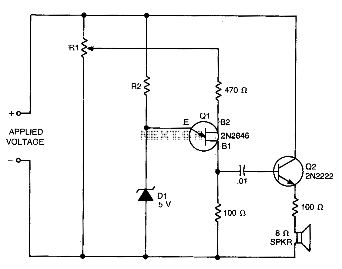
The values of R1, R2, and D1 are selected based on the voltage applied. Using a 12-volt battery, R1 is set to 10 kΩ, R2 to 5 kΩ, and D1 is a 5-volt zener diode or a string of...
In conventional white LED design, the Max1916 low-dropout bias supply for white LEDs serves as a high-performance alternative to simple ballast resistors. The Max1916 is an integrated circuit designed to provide a stable and efficient bias supply for white LEDs....
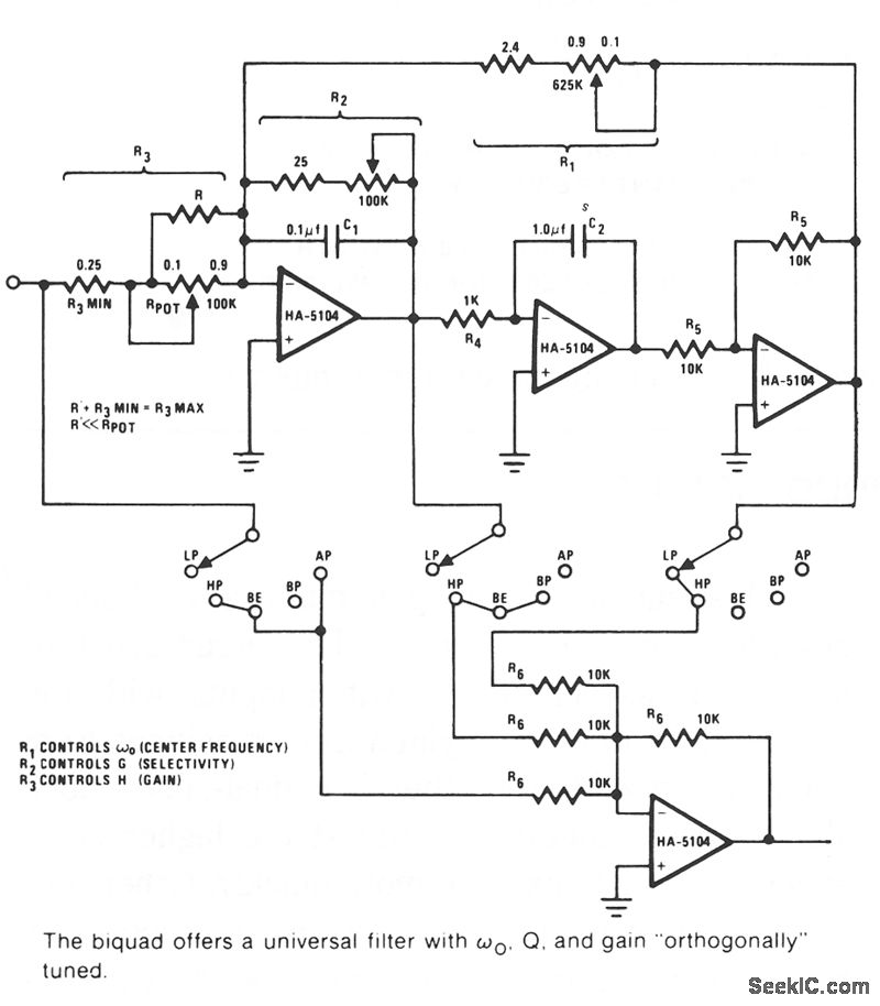
The Biquad consists of two successive integration stages followed by an inverting stage. The entire configuration includes a feedback loop from the front to the back, with resistor R1 primarily responsible for controlling the center frequency, fo. The first...
Many circuits can be powered directly from the mains with the aid of a series capacitor (C1). The disadvantage of this approach is that usually only one half cycle of the mains waveform can be used to produce a...
This is the second part of the square root algorithm. It was developed during the final stages of finishing this website and reviewing this document for publication. While Part I focused on an empirical discovery for a sequential algorithm...
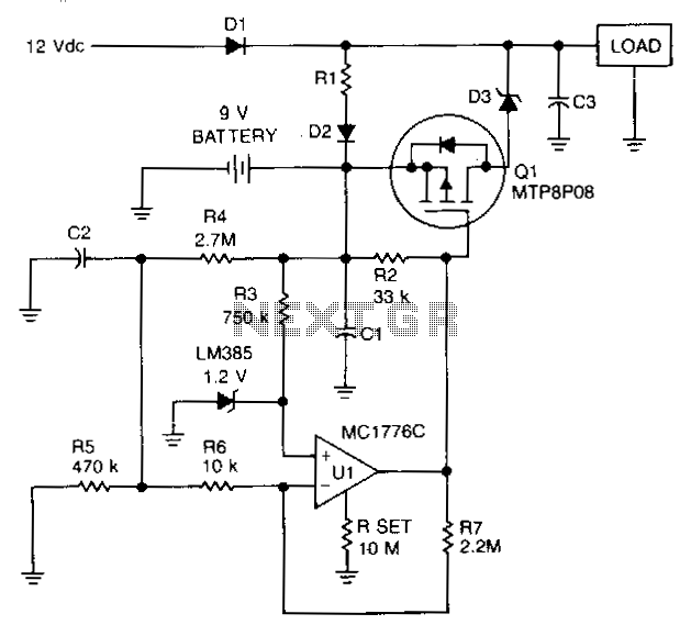
To prevent battery damage due to over-discharge, a low-voltage detector and switch should be included in the design of the battery backup circuit. The detector circuit should consume extremely low current. The switch should exhibit a low-voltage drop and...