
Low voltage detector

The circuit operates as a voltage monitoring system that utilizes a combination of resistors, a zener diode, and transistors to provide an alert when the voltage level of a battery drops below a predefined threshold. The configuration begins with a 12-volt battery supplying the circuit. Resistor R1, valued at 10 kΩ, acts as a voltage divider, setting the reference voltage for the detection mechanism. Resistor R2, at 5 kΩ, provides the necessary biasing for the zener diode D1, which regulates the voltage to approximately 5 volts. This zener diode may be replaced by a series of forward-biased silicon rectifiers that also yield a similar voltage drop.
Transistor Q1, a Unijunction Transistor, is pivotal in the detection process, triggering the alert mechanism when the voltage falls below the threshold established by R1. The second transistor, Q2, serves as a small-signal or switching NPN transistor, which amplifies the signal from Q1 to activate the speaker. The speaker generates beeps as a warning signal that corresponds to the level of undervoltage detected. The frequency of the beeping is directly proportional to the amount of voltage drop, providing a clear indication of the battery's status.
The circuit is designed to draw minimal current when the detector is connected, ensuring that it does not adversely affect the operation of other devices powered by the same battery. In scenarios where multiple voltages are monitored, it is recommended to set R1 to draw only 1 mA to 2 mA, maintaining efficiency while ensuring accurate voltage monitoring. The selection of the zener diode D1 to be around half of the desired trip voltage is critical, as it allows for optimal performance of the voltage detection circuit. Overall, this design effectively combines simplicity and functionality, making it suitable for various battery monitoring applications.The values of Rl, R2, and D1 are selected for the voltage applied. Using a 12-volt battery, Rl = 10 K, R2 = 5 K and D1 is a 5-volt zener diode, or a string of forward-biased silicon rectifiers equaling about 5 volts. Transistor Ql is a general-purpose UJT (Unijunction Transistor), and Q2 is any small-signal or switching NPN transistor.
When detector is connected across the battery terminals, it draws little current and does not interfere with other de vices powered by the battery If voltage drops below the trip voltage selected with the Rl setting, the speaker beeps a warning. The frequency of the beeps is determined by the amount of undervoltage. If other voltages are being monitored, select Rl so that it draws only 1 mA or 2 mA. Zener diode D1 is about one-half of the desired trip voltage, and R2 is selected to bias it about 1 mA.
Related Circuits

This circuit generates a TTL-compatible pulse whenever the signal falls within the limits established by the potentiometers. The circuit's configuration can be adjusted to suit specific applications. Operational amplifiers E, D, and C are utilized alongside the two potentiometers...
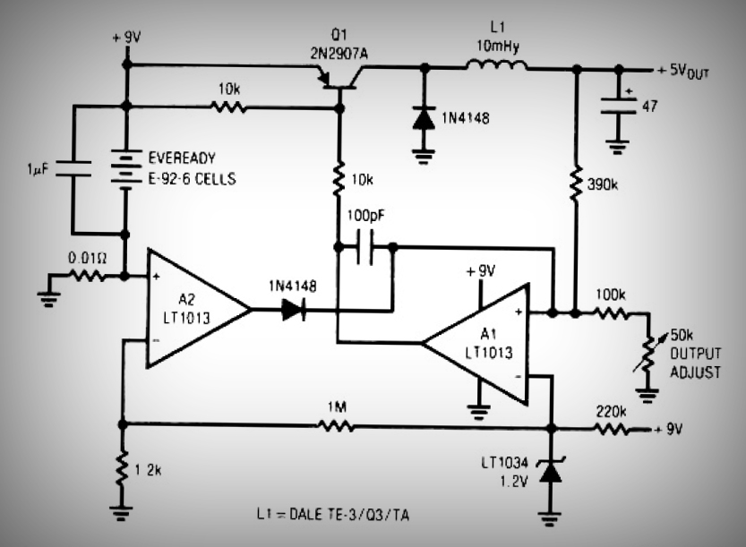
This circuit is a simple battery-powered switching regulator that provides a 5V output from a 9V source with 80% efficiency and a 50 mA output capability. When Q1 is on, its collector voltage increases, causing current to flow through...

AC solenoid DC circuit operation operates similarly to a DC contactor circuit, but the AC solenoid pull circuit is illustrated in the provided figure. The capacitance C is generally between 1-10 microfarads (µF), with a minimum of 20 microfarads...

This circuit was originally designed to detect weak flashes of laser light reflected off a fabric video projection screen. It was used as part of a firearm training system. It generates a 100 ms output pulse whenever it detects...
Until Willow Garage was acquired, there was work as a Web Robotics Engineer. This title reflects a role as a full-stack engineer focused on real-time, distributed robot control. Notable projects include an XML-RPC server and client for Node.js, a...
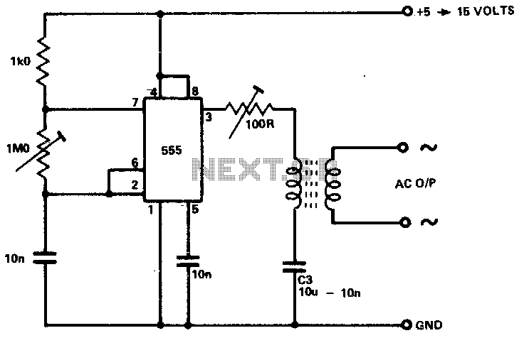
The circuit is designed to supply power for portable Geiger counters, dosimeter chargers, high resistance meters, and similar devices. The 555 timer integrated circuit (IC) operates in its multivibrator mode, with the frequency adjusted to optimize the characteristics of...