
Multiple Servomotors

The circuit design facilitates control of two servomotors through a microcontroller's port B, leveraging its I/O capabilities. Each servo is driven by a pulse width modulation (PWM) signal, which is generated using the defined pulse width variables pw1 and pw2. These variables determine the duration of the high signal in the PWM cycle, effectively controlling the position of the servos.
The first servo is connected in accordance with the configuration from the previous program, ensuring a familiar setup for users. The second servo, however, introduces additional complexity by utilizing pin B3 for its PWM signal. Pins B4 and B5 are employed for an SPDT (Single Pole Double Throw) switch, which allows for alternate control modes or functionality. This arrangement can facilitate features such as switching between different servo positions or modes of operation, enhancing the versatility of the circuit.
The routines left1, left2, right1, and right2 are specifically programmed to manage the movement of the respective servos, allowing for coordinated control based on user input or pre-defined sequences. The overall design emphasizes modularity and scalability, enabling users to expand the system further by adding more servos if additional I/O lines are available. The use of pulse width modulation is critical in ensuring smooth and precise control of the servos, making this circuit suitable for applications requiring accurate positioning, such as robotics or automated systems.Using a modified version of the last program, we can control as many servomotors as we have I/O lines on port B. In the next listing, we will control two servos in the same manner as we controlled a single servo in the previous program.
The circuit is shown in figure 4 (below). The program uses two pulsewidth variables, pw1 and pw2; and two sets o f routines, left1 and left2, right1 and right2; one for each motor. As you can see in the schematic, the first servo is wired as per the previous circuit. The second servo is now using B3 as it`s pulse out, and B4 and B5 for the SPDT switch. 🔗 External reference
Related Circuits
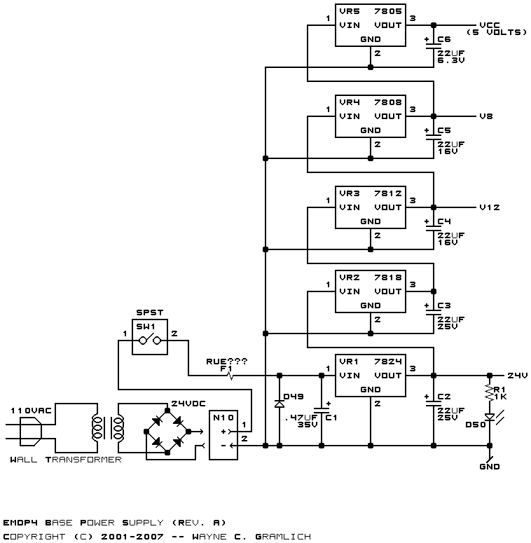
The 5-volt microcontroller interfaces with the RS-232 serial connector and the USB-B connector. It is responsible for communicating with the checker, controlling the status LEDs, and setting the voltage for the low-voltage microcontroller. The low-voltage microcontroller operates at the...
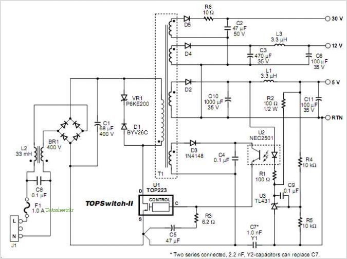
This application note describes a digital blood pressure meter concept that utilizes integrated pressure sensor analog signal-conditioning circuitry, microcontroller hardware/software, and a liquid crystal display. The sensing system measures cuff pressure (CP) and extracts pulses for analysis to determine...
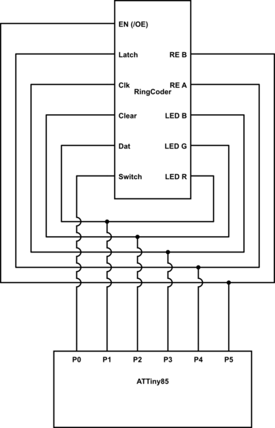
A chip conversion is being performed for the Sparkfun LED RingCoder. The sample code provided with the product functions effectively on an Arduino UNO, utilizing a separate pin for each input/output—specifically, five pins for the shift registers and six...
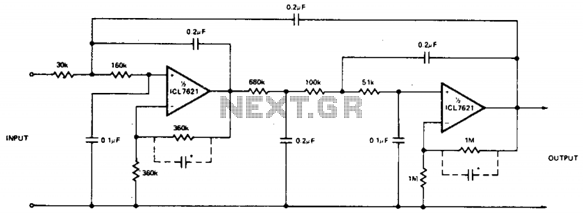
The low bias currents allow for the utilization of high resistance and low capacitance values, facilitating a low frequency cutoff at fc = 10 Hz, with an AVCL of 4 and a passband ripple of 0.1 dB. Additionally, small...
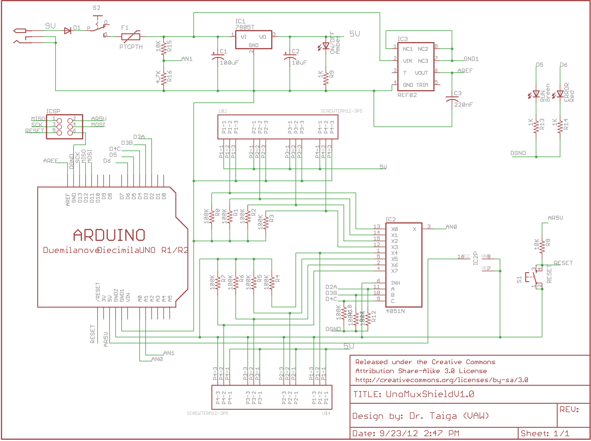
There is enthusiasm for using Arduinos in science projects. However, it is important to address several shortcomings of the Arduino before it can be utilized for more serious applications. Specifically, the addition of robust screw terminals is necessary. The Arduino...

The LA3370 is a multiplex integrated circuit (IC) designed for FM car stereo applications. It performs two primary functions using the intermediate frequency (IF) meter output voltage: 1. Stereo Noise Control (SNC), which effectively reduces noise specific to FM...