
Multivibrator infrared transmitter circuit

Transistor-based multivibrators are fundamental building blocks in electronic circuits, often used for generating square wave signals. In this configuration, transistors VT1 and VT2 operate in a feedback loop, where the charging and discharging of capacitors Ca and C2, along with the resistors Ra, R4, and Vr2, dictate the timing characteristics of the oscillation. The inclusion of diodes VD1 and VD2 ensures that the base currents are controlled effectively, preventing unwanted conduction states that could disrupt the oscillation.
The frequency of oscillation can be adjusted by varying the values of the resistors and capacitors in the circuit. For instance, increasing the capacitance of Ca or C2 or increasing the resistance values of Ra or R4 will result in a longer charge and discharge time, thereby reducing the frequency of the output signal. Conversely, decreasing these values will increase the frequency.
The output from the collectors of VT1 and VT2 is used to drive multiple LEDs, which not only serve as indicators of the circuit's operational status but also illustrate the alternating nature of the multivibrator's output. The infrared LEDs (LED2 and LED3) can be used in remote control applications or other infrared signaling tasks, while the visible LED (LEDI) provides a simple visual confirmation of the circuit's activity.
Overall, the described multivibrator circuit is a versatile and effective solution for generating oscillating signals in various electronic applications, offering both visual feedback and the potential for further integration into larger systems. By transistors VT1, VT2 and RC components, etc. to form a multivibrator. Multivibrator works: Ra, R4 are VT2, VT1 base bias resistor, closing the switch SA after the power volt age, VT2 priority conduction through its collector plate was low O this low level by VD2, Ca is coupled to the base of VT1 together make VT1 off. After VT2 conduction, R4, VD2 and Vr2 charge to G, the charge is to bring G left positive and right negative charges r make VT1 base potential starts to rise.
When the base current pressure is increased to a certain value, rri conduction, the collector under the jump substation level by VD1, C2 is added to the base VT2, VT2 by conduction to make the deadline. A moment later. VT1 turned off. VT2 conduction. VT1, VT2 variant for turning on and off, so to the cycle continues, so do the glenoid q4 multivibrator.
The oscillation frequency depends on the charge and discharge time constant and G breeze Island. VT1, VT2 after the start-up alternately turned on and off, then on its collector LED2, LED3 and LEDI alternately emit infrared light red shade.., LED visible light is used to monitor the oscillator is working properly or not, that is the working condition.
Related Circuits
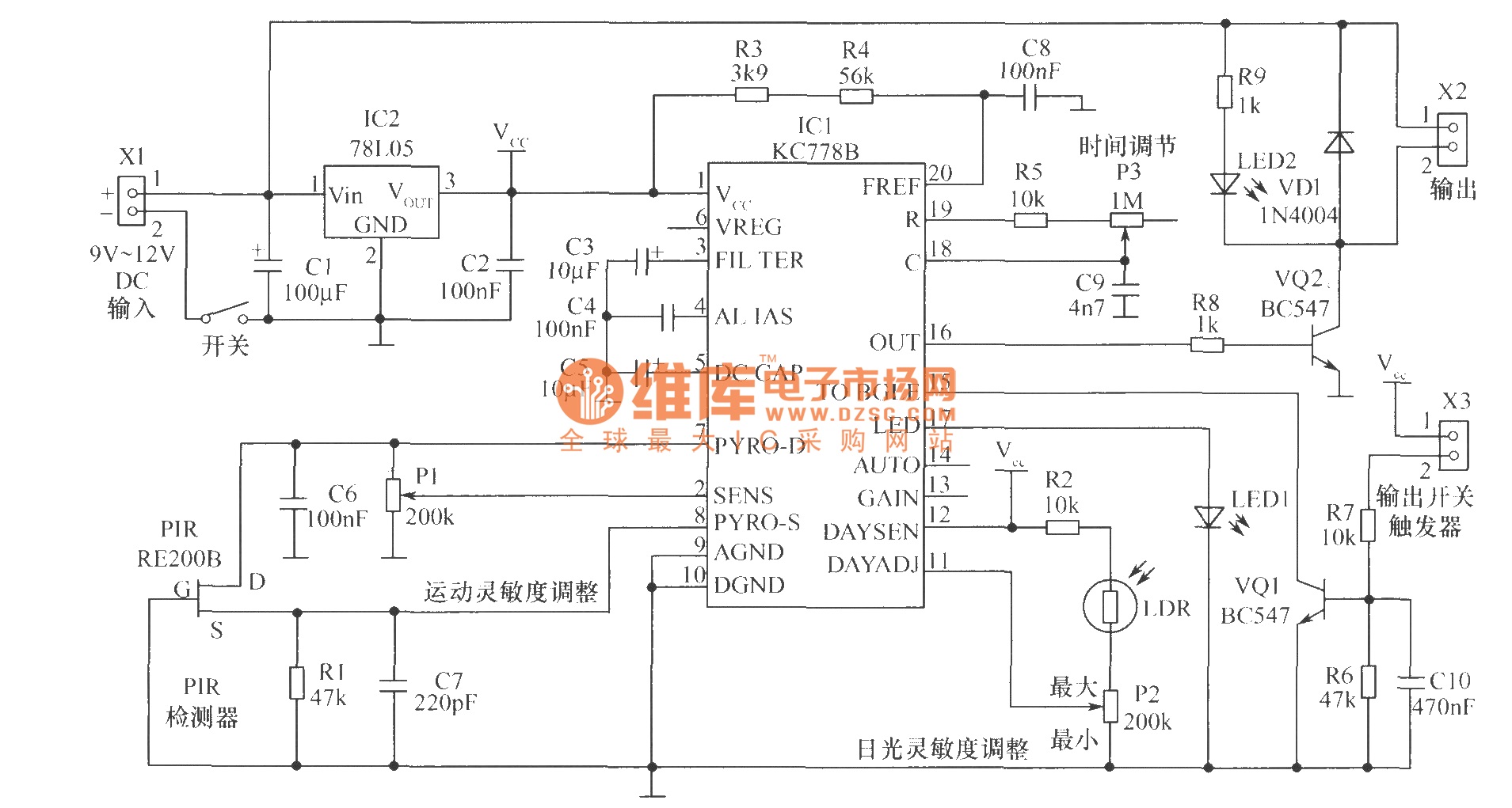
The core component of the motion detection circuit is the motion detection chip IC1 (KC778B). The signal frequency from the PIR sensor is low, ranging from 0.1Hz to 10Hz, while the bandwidth is quite broad, which the chip will...
The circuit presented is a standard Colpitts oscillator, commonly utilized in many amateur radio homebrew transmitters. This specific circuit is designed to operate effectively within a frequency range of 1500 kHz to 8000 kHz. To accommodate lower frequencies, it...
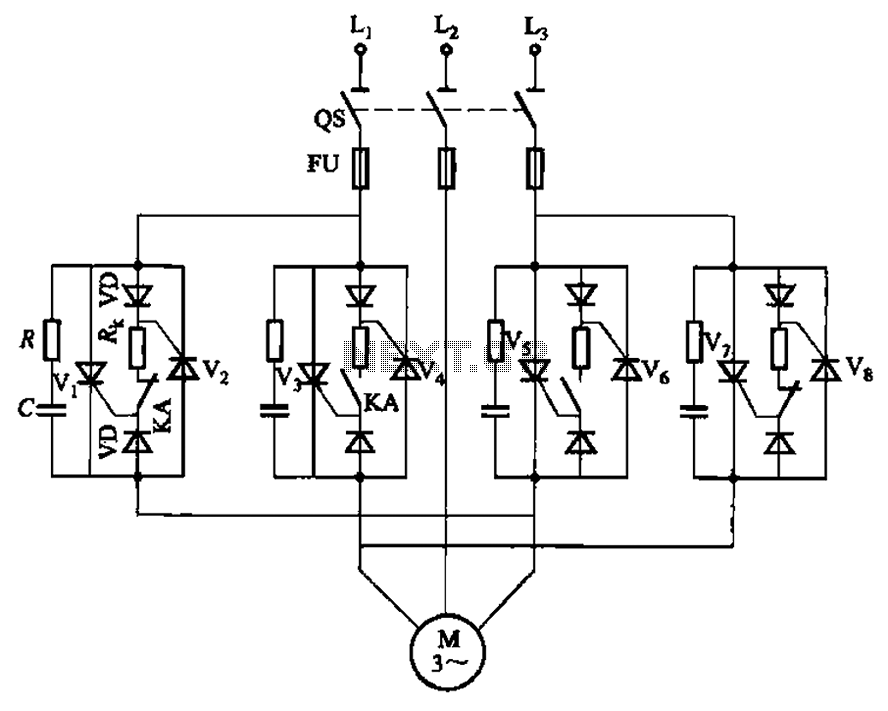
The circuit depicted in Figure 3-69 is designed for applications requiring frequent timing control for motor reversing operations. In this configuration, thyristors V1, V2, V7, and V5 are utilized for positive control of rotation, while thyristors V3, V4, and...
To enhance usability during nighttime, the receiver features a scale with bias lighting, and the surface behind the scale is coated with a fluorescent material. To activate the scale illumination, press button 3. Radio programs can be listened to...
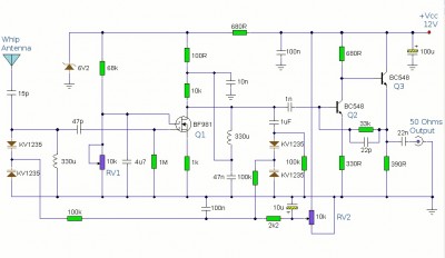
This is a booster antenna circuit designed for frequencies ranging from 550 kHz to 1650 kHz, aimed at amplifying signals received from a telescopic antenna. It covers the medium waveband within this frequency range. To drive low impedance (50...
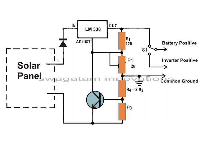
Solar panels are well-known devices that convert solar energy or sunlight into electricity. A solar panel consists of discrete sections of individual photovoltaic cells, each capable of generating a small amount of electrical power, typically between 1.5 to 3...