
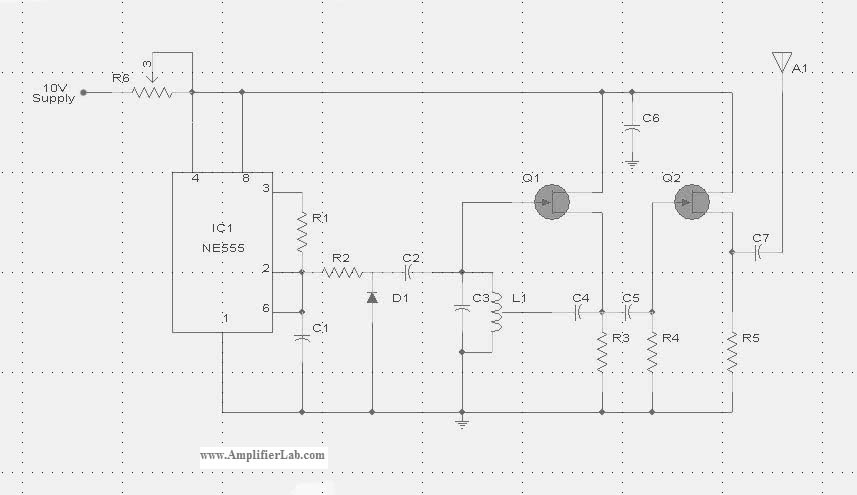
Booster Antenna Circuit 550Khz to 1650Khz

The booster antenna circuit operates effectively within the specified frequency range, utilizing a telescopic antenna as its input source. The BF981 MOSFET serves as the initial amplification stage, where its output impedance is increased through the composite configuration of Q2 and Q3. The common emitter arrangement of Q2 facilitates significant voltage amplification, while Q3's emitter follower configuration ensures that the output remains low impedance, making it suitable for connection to 50-ohm receivers.
The gain control component, RV1, allows users to fine-tune the circuit's response to varying signal strengths. This feature is particularly beneficial in scenarios where signal conditions fluctuate, enabling the circuit to adapt dynamically to weak or strong signals. The dual-gate MOSFET TR1 introduces additional versatility, as it allows for independent control of the input signal and the gain control voltage. The double-tuning mechanism, utilizing the 330 µH coil and KV1235 varicap diodes, enhances the circuit's selectivity, ensuring that it can effectively discriminate between signals within the medium waveband.
Stability is a critical aspect of the design, achieved through the inclusion of a 6.2V zener diode, which provides a regulated power supply to the MOSFET stage. This regulation helps to maintain consistent performance across varying environmental conditions. Furthermore, the design's adaptability to different frequency bands, by altering the coil values, adds to its utility, making it a versatile solution for various radio applications. Overall, this booster antenna circuit represents a well-engineered approach to signal amplification in the medium wave frequency range.Here is abooster antennacircuit for 550Khz to 1650Khz. to amplify the input from a telescopic antenna. cover the medium waveband from about 550Khz to 1650Khz. To drive low impedance (50 ohm) receivers, the medium output impedance of the BF981 stage is enhanced by the composite amplifier made from Q2 and Q3. Q2 is operating in common emitter boosti ng voltage levels by just over 2, Q3 is operating in emitter follower providing thebooster antennacircuit with low output impedance. RV1 is the gain control allowing weak signals to be amplified or strong signals to be attenuated. The control voltagebooster antennais applied to gate 2 of TR1, a dual-gate MOSFET, the signal voltage applied via gate 1; the input signal being double tuned via the 330uH coil and the two KV1235 varicap diodes at the MOSFET`s input and by the same components at the BF981 MOSFET`s drain terminal.
Both tuned circuits provide high selectivity across the entire tuning range. To aid stability the MOSFET stage is fed from a 6. 2V zener stabilized supply. Finally this active booster antenna can be used on other bands by changing the values of the 330uH coils. Here is a schematic booster antenna circuit: We aim to transmit more information by carrying articles.
Please send us an E-mail to wanghuali@hqew. net within 15 days if we are involved in the problems of article content, copyright or other problems. We will delete it soon. 🔗 External reference
Related Circuits
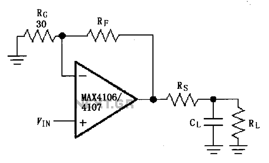
The MAX4106/4107 is designed with a capacitive load drive circuit that includes an isolation resistor (Rs). While the MAX4106/4107 exhibits excellent AC characteristics, they are not optimized for driving high reactive loads. Utilizing a high reactive load may diminish...
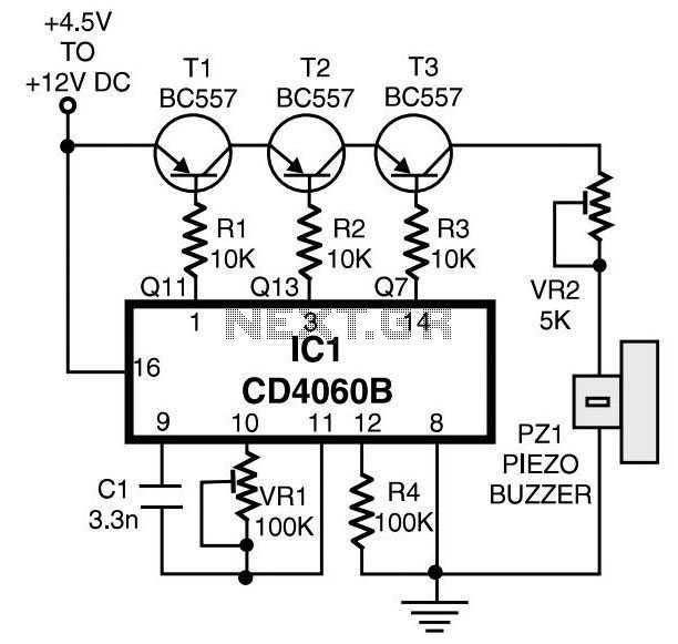
Join the forum discussion on this post. This is a simple home telephone ringtone generator circuit built using only a few electronic components. It generates a simulated telephone ringtone and requires only a DC supply. The home telephone ringtone generator...
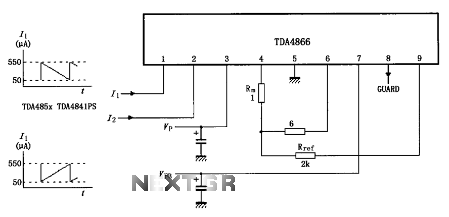
The TDA4866 test circuit operates with a positive supply voltage (VP) and a feedback voltage (VFB) in conjunction with a flyback circuit. The circuit responds to changes in the input signal, transitioning from one state to another. The input...
The circuit consists of an ultrasonic transmitter and a receiver that operate at the same frequency. Ultrasonic piezoelectric transducers serve as the output and input devices, respectively, with their frequency of operation determined by the specific devices used. The...
The circuit diagram of the Radio Collar Transmitter is presented here. This circuit is based on the NE555 integrated circuit, which serves as the central component. The Radio Collar Transmitter circuit utilizes the NE555 timer IC to generate a modulated...
The following circuit illustrates an Ultrasonic Sensor Switch circuit diagram. This circuit is based on the 555 Timer IC for the Ultrasonic Transmitter. The Ultrasonic Sensor Switch circuit utilizes a 555 Timer IC configured in astable mode to generate ultrasonic...