
Musical Envelope Generator And Modulator

The circuit described utilizes a voltage-controlled envelope generator that modulates the amplitude of a musical tone based on the gate voltage applied to the system. The initial activation of the circuit occurs with the application of a gate voltage, which determines the state of Q1. When Q1 is turned on, it allows current to flow and charge capacitor C. The attack potentiometer, in conjunction with a 1 kΩ resistor, forms an RC time constant that dictates how quickly the capacitor charges. The adjustment of the attack potentiometer enables the user to create varied sound effects, ranging from sharp, percussive sounds with a fast attack to smoother, "backward" sounds with a slower attack.
Upon the removal of the gate voltage, Q2 is activated, allowing capacitor C to discharge through the decay potentiometer and another 1 kΩ resistor, which also contributes to the decay time constant. This decay time constant is adjustable, providing further control over the sound envelope. The buffered envelope signal, facilitated by IC1, is then fed into Q3, which acts as a chopper that modulates the envelope in alignment with an incoming square wave signal at its base. The square wave's frequency dictates the intervals at which the envelope is "chopped," resulting in a waveform that combines the envelope's amplitude characteristics with the harmonic content of the square wave.
IC2 functions as a virtual earth amplifier, ensuring that the signal remains stable and properly buffered throughout the circuit. Diode D1 plays a crucial role by allowing the envelope to decay gracefully, preventing abrupt cutoffs that could result in undesirable artifacts in the audio output. This configuration provides a versatile envelope shaping mechanism suitable for various audio applications, allowing for dynamic control over sound synthesis and modulation. A gate voltage is applied to initiate the proceedings. When the gate voltage is in the ON state, Q l is turned on, and capacitor C is charged up via the attack pot in series with the l-kfl resistor. By varying this pot, the attack time constant can be manipulated. A fast attack gives a percussive sound, a slow attack gives the effect of "backward" sounds. When the gate voltage returns to its OFF state, Q2 is turned on and the capacitor is then discharged via the decay pot and the other 1-KOhmhm resistor to ground. Thus, the decay time constant of the envelope is also variable. This envelope is buffered by IC1, a high-impedance voltage follower and is applied to Q3, which is being used as a transistor chopper.
A musical tone in the form of a square wave is connected to the base of Q3. This turns the transistor on or off. Thus, the envelope is chopped up at regular intervals, which are determined by the pitch of the square wave. The resultant waveform has the amplitude of the envelope and the harmonic structure of the square wave.
IC2 is used as a virtual earth amplifier to buffer the signal and D1 ensures that the envelope dies away at the end of a note.
Related Circuits
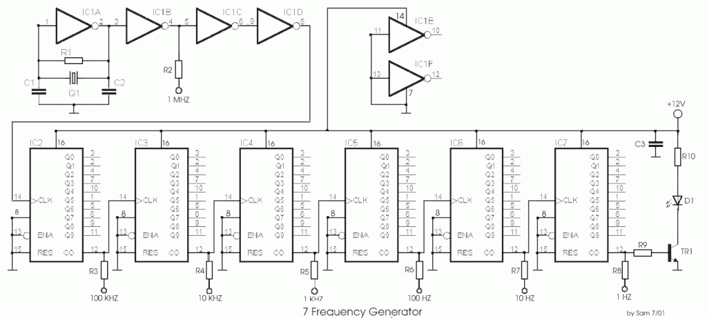
The circuit was designed to create a frequency generator that consists of seven steps during operation. It includes a crystal oscillator, which is an electronic circuit made of... The frequency generator circuit operates through a series of seven distinct steps,...
A useful feature of this circuit is that the frequency can be changed by modifying the capacitor value. A switch can be added to select between various frequencies. This circuit utilizes a capacitor in conjunction with an oscillator to determine...
A friend requires a pulse generator oscillator circuit that maintains a stable frequency of 32.768 kHz for a digital CMOS binary counter. The pulse generator oscillator circuit designed to operate at a frequency of 32.768 kHz is commonly used in...
As shown in the generator start battery automatic monitor circuit diagram. The generator start battery automatic monitor circuit is designed to oversee the battery's status during generator operation. This circuit ensures that the battery remains charged and functional, preventing premature...
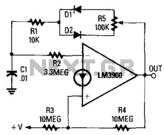
The circuit integrates a charging mechanism through Rl/Dl and the upper half of R5, while discharging occurs via R1/D2 and the lower half of R5. The duty cycle is adjustable within a range of 1:10 to 10:1 through the...
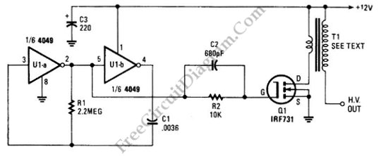
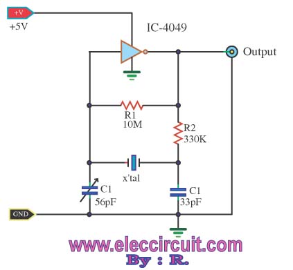
The schematic diagram below illustrates a circuit for a high voltage generator. This circuit employs a 4049 hex inverter as an oscillator, and it can be utilized for ignition purposes. The high voltage generator circuit is designed to convert a...