
7 Standard Step Frequency from Frequency Generator

The frequency generator circuit operates through a series of seven distinct steps, each contributing to the overall functionality of the device. The heart of this circuit is the crystal oscillator, which provides a stable frequency reference. The crystal oscillator utilizes a quartz crystal to generate precise oscillations when an AC voltage is applied. This stability is crucial for applications requiring accurate timing and frequency generation.
The first step in the operation involves the initialization of the power supply, ensuring that all components receive the necessary voltage levels for optimal performance. Following initialization, the second step activates the crystal oscillator, which begins to oscillate at its fundamental frequency determined by the physical properties of the quartz crystal.
In the third step, the output from the crystal oscillator is fed into a buffer amplifier. This stage is essential for isolating the oscillator from the subsequent stages, preventing loading effects that could alter the frequency stability. The buffer amplifier also provides a stronger signal suitable for driving further circuit components.
The fourth step involves frequency division, where the output frequency from the buffer amplifier is divided down to a lower frequency using flip-flops or counters. This division is critical for generating various frequencies required for different applications, such as modulation or timing signals.
In the fifth step, a low-pass filter may be employed to smooth the output signal, removing any high-frequency noise that could interfere with the intended signal integrity. The filtering ensures that the final output is clean and suitable for further processing or use.
The sixth step is the amplification of the filtered signal. An additional amplifier stage can be used to increase the output signal's amplitude, making it suitable for driving loads or interfacing with other circuits.
Finally, the seventh step involves outputting the generated frequency signal through a suitable interface, which could be a simple output pin or a more complex connector, depending on the application requirements. This output can then be utilized in various electronic applications, such as clock generation, signal modulation, or frequency synthesis.
Overall, the design of this frequency generator circuit emphasizes stability, flexibility, and ease of integration into larger systems, making it a valuable component in various electronic applications.The circuit was designed to create a frequency generator that consists of 7 steps during the operation. Crystal Oscillator an electronic circuit made of.. 🔗 External reference
Related Circuits
This circuit measures the distance covered during a walk. Hardware is located in a small box slipped in pants pocket and the display is conceived in the following manner: the leftmost display D2 (the most significant digit) shows 0...
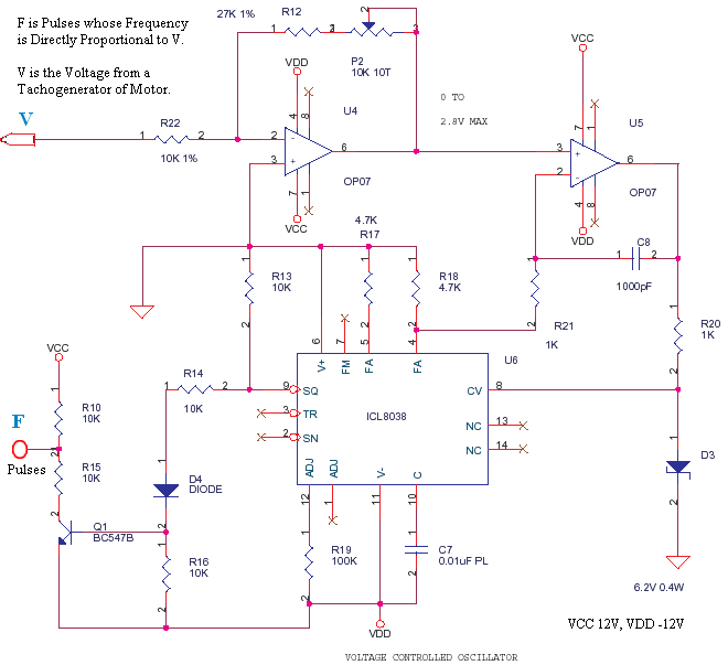
This is a small circuit designed to drive an impact counter, with the central component being the ICL8038. The circuit is intended for use with a motor that drives a conveyor, which includes a feedback mechanism known as a...
The two circuits below illustrate the generation of low-frequency sine waves by shifting the phase of the signal through an RC network, ensuring that oscillation occurs when the total phase shift reaches 360 degrees. The transistor circuit on the...
A basic square wave generator has been designed to operate a speedometer circuit board, which is responsible for controlling various functions. The square wave generator circuit typically consists of a few key components: a timer IC, such as the 555...
The purpose of this application note is to present an example circuit illustrating the operation of the XR-T5683 device at a data rate of 10.1 Mbps. This note includes the results of measurements taken on the XR-T5683 at this...
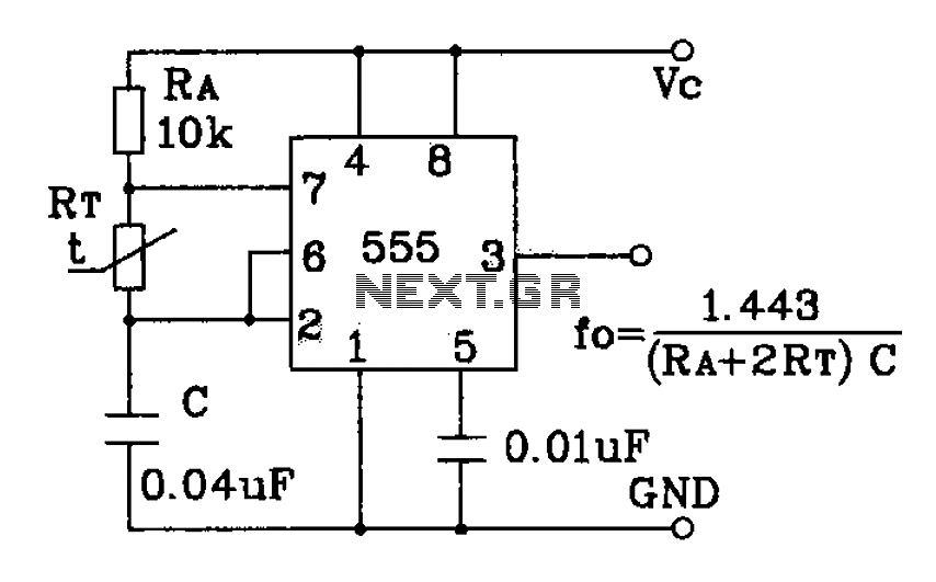
555 precision temperature sensor with temperature frequency converting circuit diagram consisting of: The 555 precision temperature sensor operates by converting temperature variations into frequency signals. This circuit typically utilizes a 555 timer IC configured in astable mode to generate...