
(N + 1) Wires Connect N Hall-Effect Switches
 Wires Connect N Hall-Effect Switches")
The circuit utilizes Hall-effect switches for their advantages, such as immunity to dust and moisture, and the absence of mechanical wear. The configuration of IC1A as a current-to-voltage converter is crucial for transforming the sensor output into a usable voltage signal. This setup allows for precise monitoring of the current changes that occur when the Hall-effect switch is actuated. The output from IC1A is fed into IC1B, which is configured as a comparator. This comparator is responsible for comparing the output voltage with a reference voltage. When the output current from the Hall-effect switch increases, indicating activation, IC1B detects this change and provides a low output signal, indicating that the switch is engaged.
The fault-detection feature enhances the reliability of the circuit by providing visual feedback through the use of LEDs. Each LED corresponds to a specific sensor output wire, allowing for easy identification of faults in the system. If a wire becomes open, the associated LED lights up, providing immediate notification of the issue. Similarly, if there is a power failure or short circuit, multiple indicators will activate, enhancing the diagnostic capabilities of the circuit.
Transistor Q1 plays a critical role in the alarm system. When an LED is illuminated due to a fault condition, Q1 is activated, which can energize the alarm relay, triggering an alert. This mechanism ensures that any fault conditions are promptly addressed, improving the overall safety and reliability of the system. The design effectively minimizes wiring requirements while maintaining functionality and providing essential fault detection, making it a robust solution for applications utilizing Hall-effect switches. Hall-effect switches have several advantages over mechanically and optically coupled switches. Their major drawback is that they require three wires per device. This circuit, however, reduces this wire count to N+1 wires for devices. Amplifier IC1A is configured as a current-to-voltage converter. It senses the sensor assembly"s output current. When the Hall-effect switch is actuated, the sensor"s output current increases to twice its quiescent value. Amplifier IC1B, configured as a comparator, detects this increase. The comparator"s output goes low when the Hall-effect switch turns on. The circuit also contains a fault-detection function. If any sensor output wire is open, its corresponding LED will turn on. If the power-supply line opens, several LEDs will turn on. A short circuit will also turn an LED on. Every time an LED turns on, Ql turns on and the alarm relay is actuated.
Related Circuits
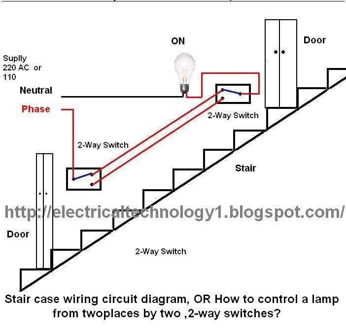
The circuit is complete, and the bulb is ON. To turn OFF the bulb from the upper switch at the top of the stairs, simply turn OFF the switch, which will break the circuit and turn the bulb OFF....
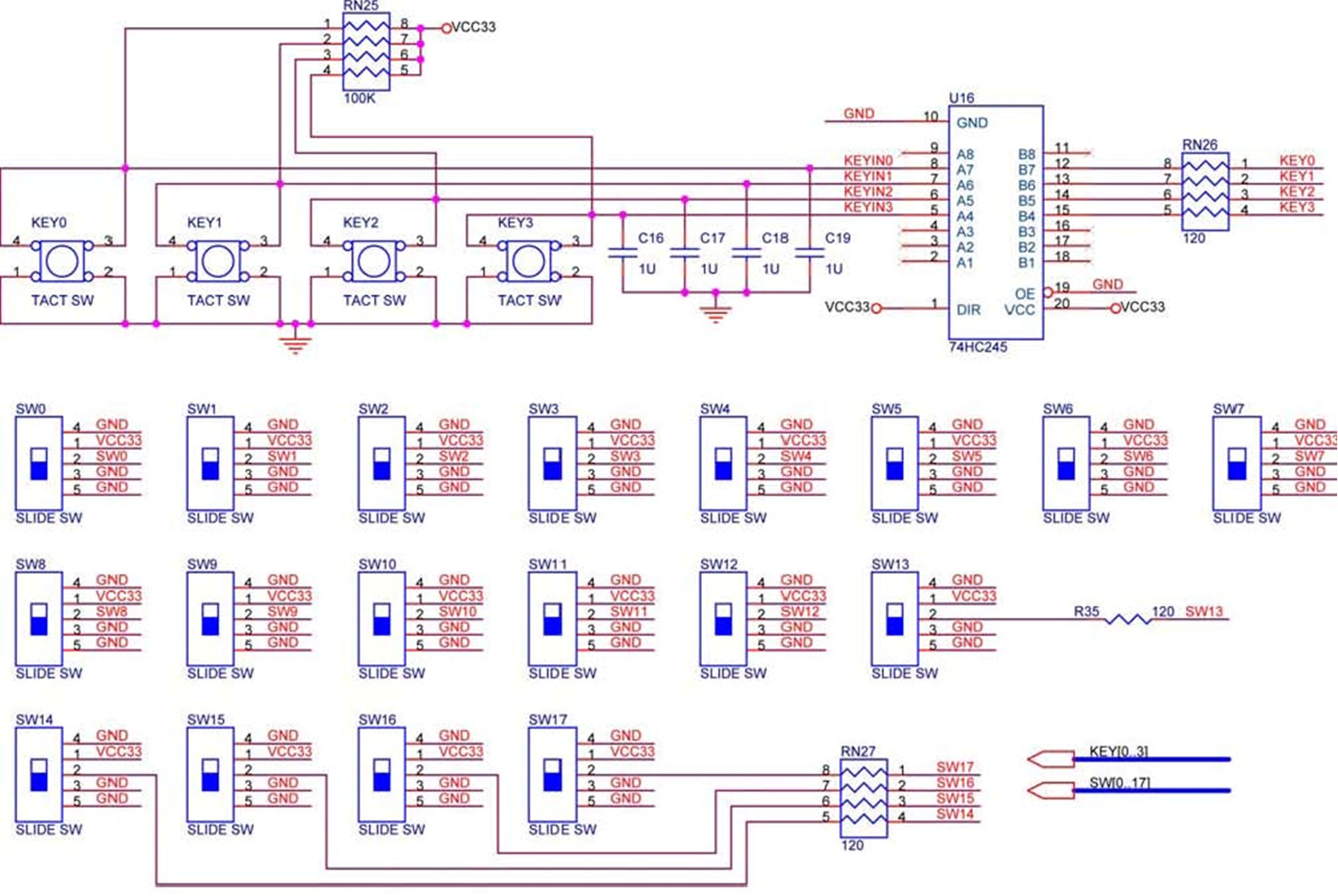
The DE2 board features four pushbutton switches, each of which is debounced using a Schmitt Trigger circuit, as shown in Figure 1. The outputs, labeled KEY0 to KEY3, from the Schmitt Trigger are directly connected to the Cyclone II...
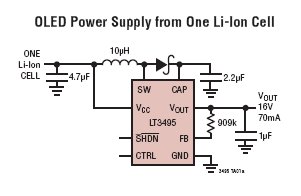
The LT3495, LT3495B, LT3495-1, and LT3495B-1 are low-noise boost converters equipped with an integrated power switch, feedback resistor, and output disconnect circuitry. These devices manage power delivery by adjusting both the peak inductor current and the switch off-time, resulting...
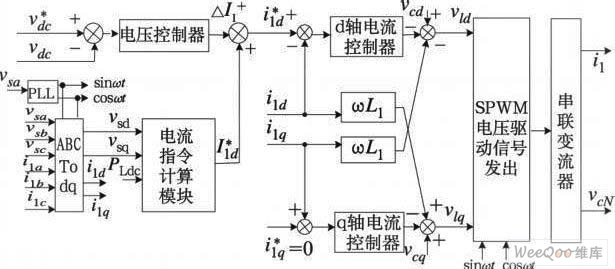
The demand for high-quality electric energy in modern industrial development is increasing, making it essential to provide safe and reliable green power to energy consumers. Uninterruptible Power Supplies (UPS) are crucial for improving electric energy quality and ensuring the...

The objective of this project was to investigate the wireless linkage of objects, locations, and individuals. Initial discussions revolved around the intended use of the project—whether for private or public purposes—and the number of participants involved. Considerations included the...
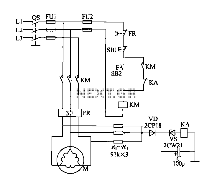
Delta connection motor phase failure protection circuit is illustrated in the figure. Its protective function involves three resistors, R1, R2, and R3, which are connected to form an artificial neutral point. When a motor phase failure occurs, an offset...