
Narrow band receiver with MC13136

To make the 45.181250MHz crystal oscillate at the correct frequency, a coil and a resistor are added. The coil will make the crystal oscillate at its 3rd overtone. The value of the coil may need to be adjusted to set the frequency accurately. It has been noted that the oscillator frequency can vary about 600Hz if the coil value changes from 550nH to 650nH. To ensure that the Local oscillator is functioning correctly, a frequency counter or an oscilloscope should be attached to pin 3 of the MC13136, and the coil should be adjusted accordingly. In the example provided, the measured frequency was 44.181345MHz. Additionally, the 10.245MHz oscillator can be monitored at pin 6.
The FM receiver operates through a dual conversion process, starting with the RF signal at 79.6625 MHz. The first local oscillator (LO) frequency is derived from a crystal oscillator operating at 45.181250 MHz, which is set to its 3rd overtone using an external coil and resistor for fine-tuning. The mixing process occurs in the first mixer stage, where the RF signal and the LO signal interact to produce an intermediate frequency (IF) of 10.7 MHz. This IF signal is then filtered and fed into a second mixer stage, where it is mixed with a second crystal oscillator operating at 10.245 MHz. The output of this stage is a further down-converted frequency of 455 kHz, which is processed through a narrowband filter to remove unwanted signals before being sent to the FM detector for demodulation.
The design emphasizes low-voltage operation, allowing for a voltage range of 2-6 VDC, making it suitable for battery-powered applications. The receiver also incorporates a voltage buffered Received Signal Strength Indicator (RSSI) with a dynamic range of 70 dB, providing valuable feedback on signal strength. The use of a CMOS PLL synthesizer allows for precise tuning and stability of the local oscillator, ensuring reliable performance across the specified frequency range of 0-200 MHz. The careful selection of components and the attention to oscillator stability are critical for achieving optimal reception quality in various operating conditions.Complete Dual Conversion FM Receiver. Input frequency range 0-200MHz. Voltage byffered RSSI with 70 dbof usable range. Low voltage operation 2-6 VDC. VHF Collpits First LO for Crystal or VCO operation. Isolated Tuning diod. Buffered first LO output to drive cmos PLL sythesizer. This receiver is built to receive at 79.6625MHz. If you want to receive at other frequency you must get a crystal for that frequency. You can still follow the text below, but the calculation will different for different crystals. The frequency I want to receive is 79.6625MHz. The crystal I am using is a 3:e overtone witch oscillate at 45.181250MHz. Attach a frequency counter to pin 3 if you want to measure the frequency. This is the exact half frequency that I want to receive. In the receiver mixer the RF (79.6625MHz) will mix with the Local oscillator (45.181250MHz) and also with the double frequency of the Local oscillator (90.3625MHz). The product of the frequencies will be : 2* 45.18125MHz - 79.6625MHz = 10.7MHz (fig below). This signal will appear at pin 20 on the MC13136. After passing a filter the IF signal enters mixer 2 and mixes with the 10.245MHz Crystal oscillator. The product is a 455kHz signal at pin 7. The 455kHz signal will pass a narrowband filter and then enter the FM detector. To make the 45.181250MHz crystal oscillate at correct frequency I add a coil and a resistor (Fig below). The coil will make the crystal to oscillate at its 3:e overton. You might have to adjust the value of the coil to set the frequency right. I noticed that the ocillator will vary about 600Hz if the coil value changes from 550nH to 650nH. To be sure that your Local oscillator works, attach a frequency-counter or a oscilloscop to pin 3 at MC13136 and adjust the coil.
In my example I measured 44.181345MHz. You can also controll the 10.245MHz oscillator at pin 6. 🔗 External reference
Related Circuits
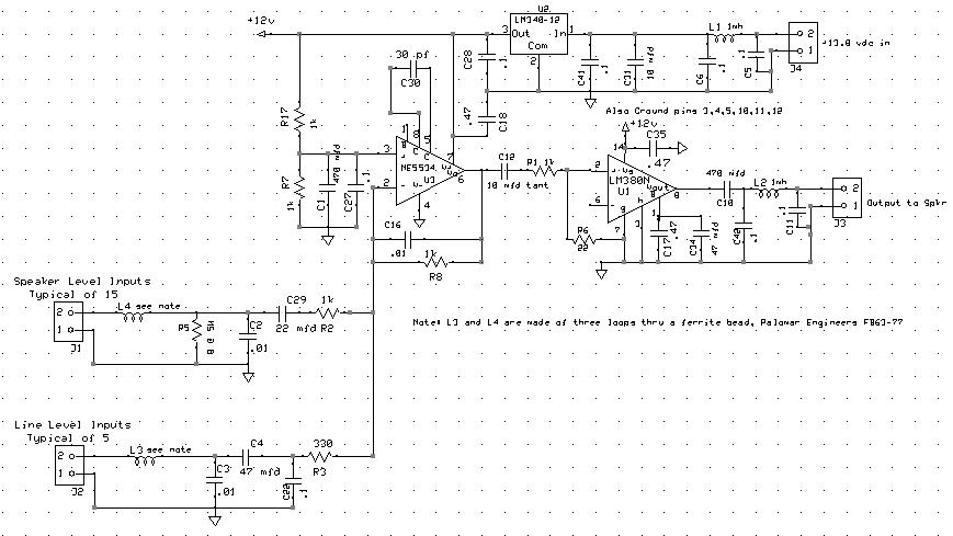
The audio mixer allows for easy comparison of various receivers by adjusting the gain controls without the need for switching. This setup simplifies A/B comparisons since all receivers are connected to the same antenna. Previously, different speakers were used...
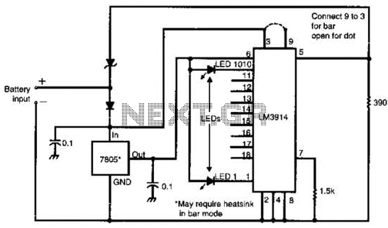
Many amateur receivers are equipped with an S meter that does not operate logarithmically. The proposed circuit is intended to enhance such receivers. Although integrated circuits like the CA3089 or CA3189 are not commonly used today, they play a...
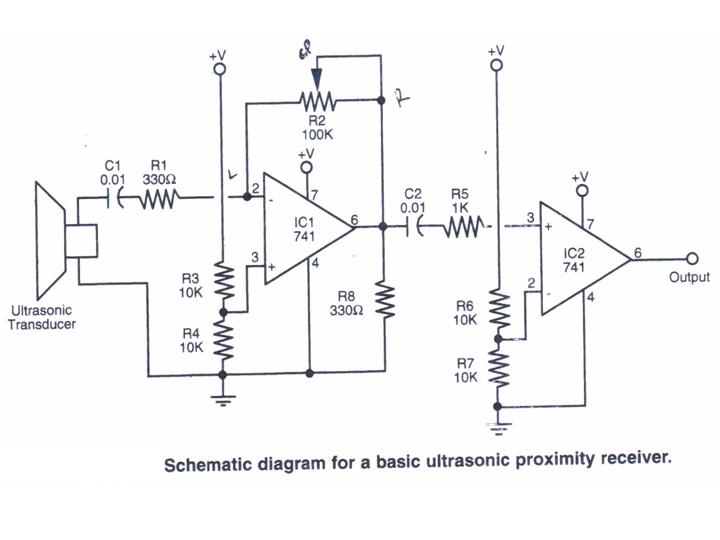
This section provides step-by-step instructions, accompanied by photos, for constructing an Ultrasonic Proximity Receiver. As this circuit is quite simple, only a schematic for the sensor is presented here. The objective of this tutorial is to assist others in...
This document outlines the hardware modifications required to adapt a Kenwood TK-931 transceiver for 902 MHz repeater receive operation. It does not include the programming effort needed for the desired operating frequency, which can be performed using Kenwood KPG-5D...
The circuit was designed to create ten different frequency bands that can be processed by a single graphic equalizer to produce and maintain a predetermined frequency response. The described circuit is a graphic equalizer that utilizes a multi-band approach to...
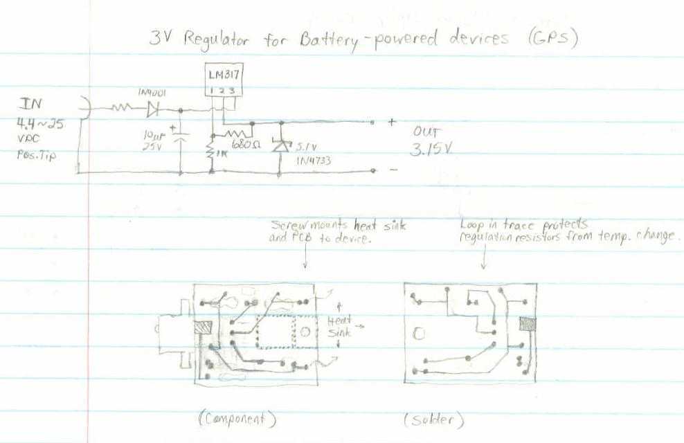
This GPS receiver is powered by 2 AA batteries. They are only strong enough for the GPS to stay on for about two hours, and this seems like quite a waste. I would like to be able to use...