
GPS receiver

The described GPS receiver circuit utilizes two AA batteries as its primary power source. The nominal voltage of two AA batteries in series is approximately 3V, which is typically sufficient for low-power GPS modules. However, the limited capacity of AA batteries results in a relatively short operational time of about two hours, indicating that the current draw of the GPS receiver is significant compared to the battery's energy storage.
To enhance the operational time and versatility of the GPS receiver, it is advisable to design a power management circuit that accommodates a larger battery or an AC adapter. This can be achieved by integrating a DC-DC boost converter that can step up the voltage from a larger battery pack (for instance, a lithium-ion battery) or directly from an AC adapter to the required operating voltage of the GPS module.
The power management circuit should include the following components:
1. **Battery Management System (BMS)**: If a lithium-ion battery pack is utilized, a BMS is essential for monitoring battery health, balancing the cells, and providing overcharge and over-discharge protection.
2. **DC-DC Boost Converter**: This component will convert the higher voltage from the battery or AC adapter to the appropriate voltage level required by the GPS receiver. The boost converter should be selected based on the current requirements of the GPS module to ensure efficient operation.
3. **Power Supply Input**: For the AC adapter, a rectifier circuit will be necessary to convert AC voltage to DC. This can include a transformer if the input AC voltage is higher than the desired output voltage.
4. **Capacitors and Inductors**: These passive components will be used in the boost converter circuit for smoothing and filtering purposes, ensuring stable voltage output to the GPS module.
5. **Protection Diodes**: To prevent reverse polarity connections and protect the circuit from potential damage, diodes should be included in the design.
By implementing this revised power supply system, the GPS receiver can achieve extended operational time and flexibility, allowing for both portable use with larger batteries and stationary use with an AC adapter. The overall efficiency of the circuit will improve, reducing energy waste and enhancing the user experience.This GPS receiver is powered by 2 AA batteries. They are only strong enough for the GPS to stay on for about two hours, and this seems like quite a waste. I would like to be able to use a larger battery, and sometimes even an AC adapter. 🔗 External reference
Related Circuits
Here are the schematics for infrared remotes. This remote transmits a tone using an infrared LED. This tone is decoded by the receiver. Since the receiver only switches when it "hears" the tone, there are no accidental activations. The schematic...
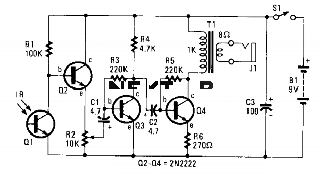
The circuit consists of Q1, a phototransistor that responds to an intensity of amplitude-modulated infrared light source, and a three-stage, high-gain audio amplifier. Transformer T1 is utilized to match the output impedance of the receiver to modern low-impedance (low-Z)...
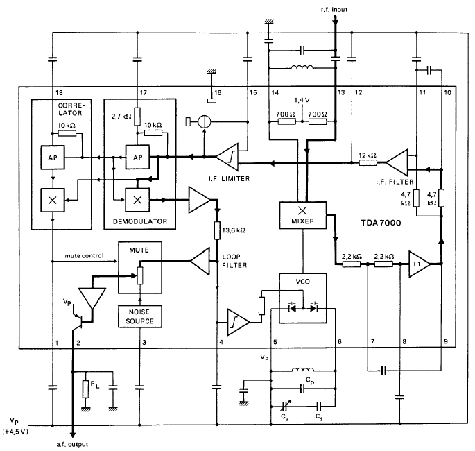
GENERAL DESCRIPTION The TDA7000 is a monolithic integrated circuit designed for mono FM portable radios or receivers, emphasizing minimal peripheral components to achieve compact dimensions and reduced costs. This integrated circuit features a Frequency-Locked-Loop (FLL) system with an intermediate...
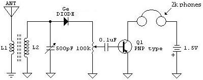
The following schematic illustrates a Crystal Radio Receiver Circuit Diagram that incorporates audio frequency (AF) amplification utilizing a Germanium transistor. The inclusion of AF amplification enhances the audio output quality. The Crystal Radio Receiver Circuit is a simple yet effective...
This is a general purpose serial port infrared receiver. With the help of appropriate software, you can control different functions of your PC from a distance. For example, you can control your home cinema settings (volume, play, pause, stop,...
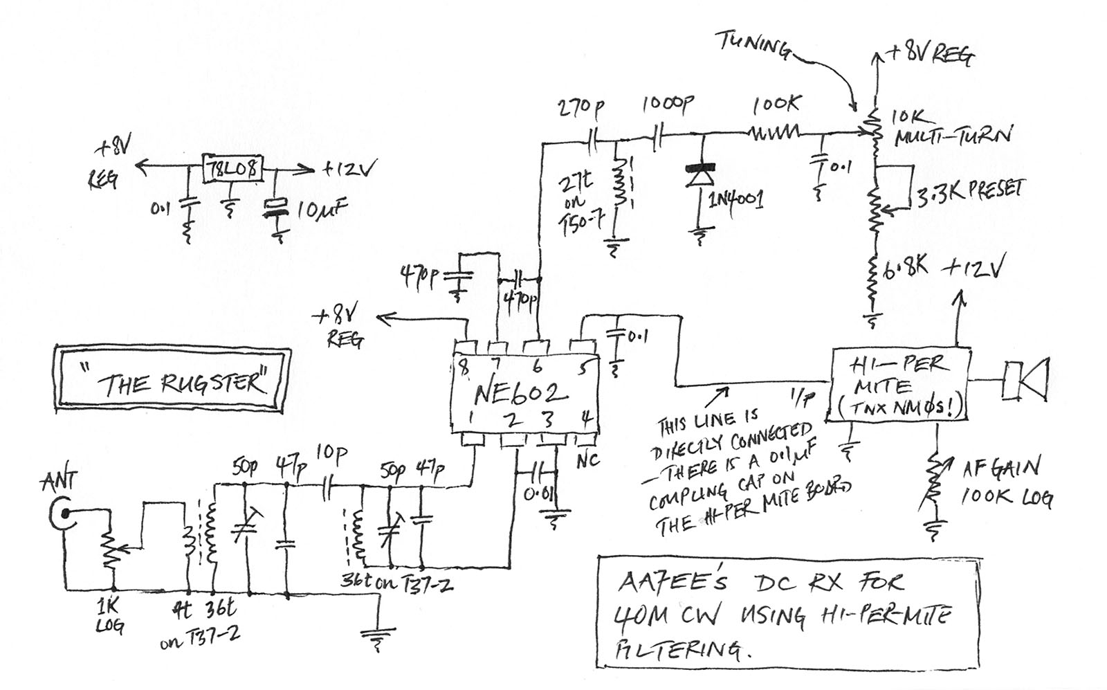
A few weeks ago, Jason NT7S mentioned the ZL2BMI DSB transceiver as a rig that might be of interest for building. He was correct; it had been seen in SPRAT, but for some reason, it had not been seriously...