
ultrasonic receiver

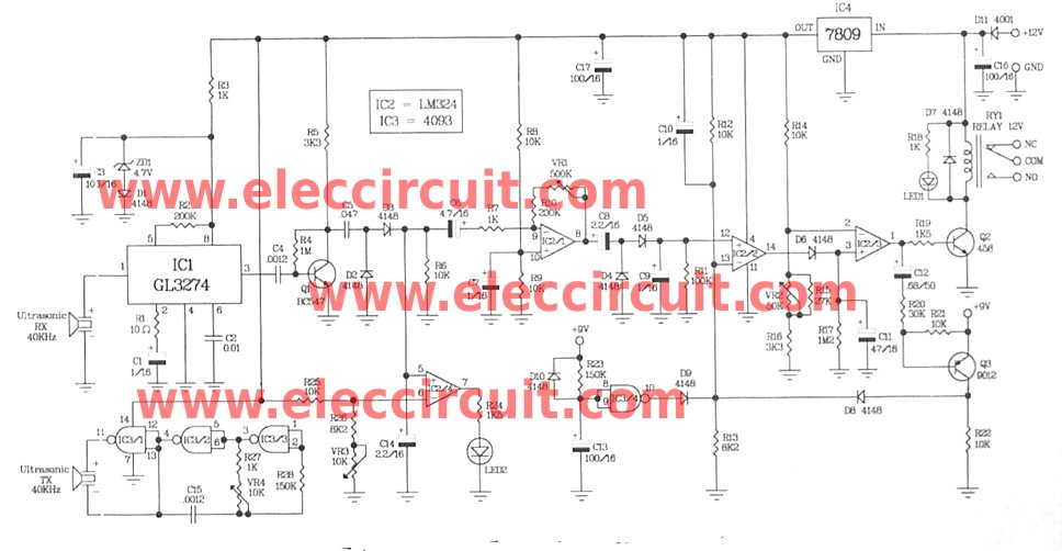
The Ultrasonic Proximity Receiver circuit operates by emitting high-frequency sound waves using an ultrasonic transmitter. These sound waves travel through the air and bounce off nearby objects. The receiver detects the reflected sound waves and calculates the distance to the object based on the time it takes for the sound waves to return.
The essential components of the circuit include an ultrasonic transmitter, typically a piezoelectric transducer, and an ultrasonic receiver, which is also a piezoelectric device. The transmitter is connected to a microcontroller or a timer circuit that generates the ultrasonic pulses. The receiver is connected to an amplifier circuit to boost the weak signals received from the reflected sound waves.
The schematic diagram typically illustrates the connections between these components, including power supply lines, ground connections, and signal paths. It is crucial to ensure that the transmitter and receiver are positioned correctly to maximize the detection range and accuracy.
In addition to the basic components, additional circuitry may be included for signal processing, such as filters to eliminate noise and microcontrollers for interpreting the distance measurements. The tutorial provides comprehensive construction details, including recommended component values, layout tips, and soldering techniques.
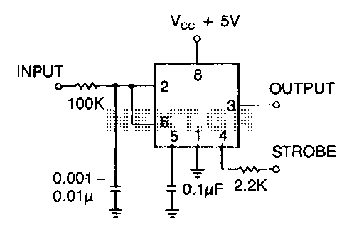
Photographic documentation throughout the tutorial aids in visualizing each step of the assembly process, ensuring that users can follow along easily. By the end of the tutorial, users will have a fully functional ultrasonic proximity receiver that can be integrated into various robotic applications, enhancing the robot's ability to navigate and interact with its environment.This section gives step-by-step instructions along with photos to the construction of Ultrasonic Proximity Receiver. Because this is a very simple circuit, only a schematic for the sensor is shown here: (For the PDF format click here.
) This tutorial`s objective was to help others built a ultrasonic proximity receiver which combined with a ultrason ic transmitter will be used as the eyes of a robot. Complete construction details and photos are included in this tutorial for the sensor. Once the concepts are conveyed the reader should be able to build their own sensor. 🔗 External reference
Related Circuits
Most telephone equipment today utilizes a DTMF receiver integrated circuit (IC). A widely used DTMF receiver IC is the Motorola MT8870, which is commonly found in electronic communication circuits. The MT8870 is an 18-pin IC employed in telephones and...
The motion sensor circuit depicted in Figure 1 operates when a 12-volt power supply is applied to the input point. The motion sensor circuit is designed to detect movement and trigger a response based on the presence of motion...
The alarm detector circuit operates differently from the Ultrasonic Alarm (1). In Ultrasonic Alarm (1), an alarm output is triggered by the detection of a reflected wave from an object during the setup time. Conversely, in this circuit, an...
Many audio systems consist of separate units, where typically only the amplifier is equipped with a remote control receiver module for economic reasons. Control signals are then transmitted to other units using patch cables. For instance, the tuner and...

This is a straightforward and easy-to-construct infrared (IR) receiver circuit. The circuit utilizes only a few components and is capable of receiving a 38 kHz carrier signal. The operation of this circuit is simple; whenever the IR LED detects...
This timer serves as an effective line receiver for control applications that involve relatively slow electromechanical devices. It operates without the need for special drivers over single, unshielded lines. The timer circuit is designed to facilitate communication between control systems...