
Nature simulator with 555 circuit

The circuit described utilizes the NE555 timer IC in its astable mode, which is a popular configuration for generating continuous square wave signals. In this setup, the timing components, which include resistors R and RP and capacitor C3, determine the frequency and duty cycle of the output waveform. The output signal from pin 3 of the NE555 is a square wave that alternates between high and low states at a frequency defined by the values of R, RP, and C3.
The current-limiting resistor R2 is crucial as it protects the TRIAC from excessive current that could otherwise damage it. The TRIAC, a semiconductor device that can control AC loads, is connected to the output to manage the power supplied to the fan. When the NE555 outputs a high signal, the TRIAC is triggered, allowing current to flow to the fan. Conversely, when the signal is low, the TRIAC turns off, interrupting the current flow and stopping the fan.
This circuit is particularly useful for applications requiring fan control based on specific timing intervals. By adjusting the values of R, RP, and C3, the frequency of the oscillation can be modified, thus changing how frequently the fan operates. This flexibility makes the circuit suitable for various cooling and ventilation applications, where intermittent fan operation is desired to save energy or manage temperature effectively. Proper heat dissipation measures should be considered in the design to ensure reliable operation of the TRIAC and the overall circuit.Circuit works: an integrated circuit lC (NE555) and R, RP, C3 substandard elements constituting around astable multivibrator, lC 3 feet square wave oscillation signal output from the current limiting resistor R2 is added to the TRIAC vs the control terminal, connected to the outlet to control the fan inside xs make it work according to the oscillation signal intermittently
Related Circuits
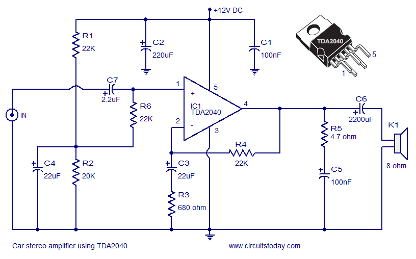
A car stereo amplifier circuit utilizing the TDA2040 is presented here. The TDA2040 is a monolithic integrated audio amplifier that functions in Class AB mode. This integrated circuit features built-in short circuit protection and thermal shutdown capabilities, and it...
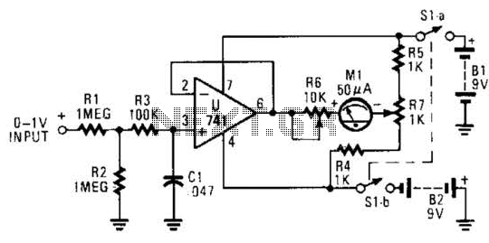
The circuit is designed around a 741 general-purpose operational amplifier (op amp) configured as a voltage follower, providing a voltage gain of one. The output from the 741 is utilized to drive a 50-meter movement. Potentiometer R7 is employed...
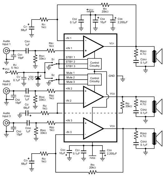
The LM4782 utilizes a protection system known as National Self Peak Instantaneous Temperature (Ke) (SPiKeTM). SPiKe safeguards the output of the LM4782 against over-voltage on the load, short circuits to ground, and provides temperature protection by monitoring instantaneous temperature....
The example below illustrates using an op-amp as an audio amplifier for a simple intercom. A small 8 ohm speaker is used as a microphone which is coupled to the op-amp input through a 0.1uF capacitor. The speaker is...
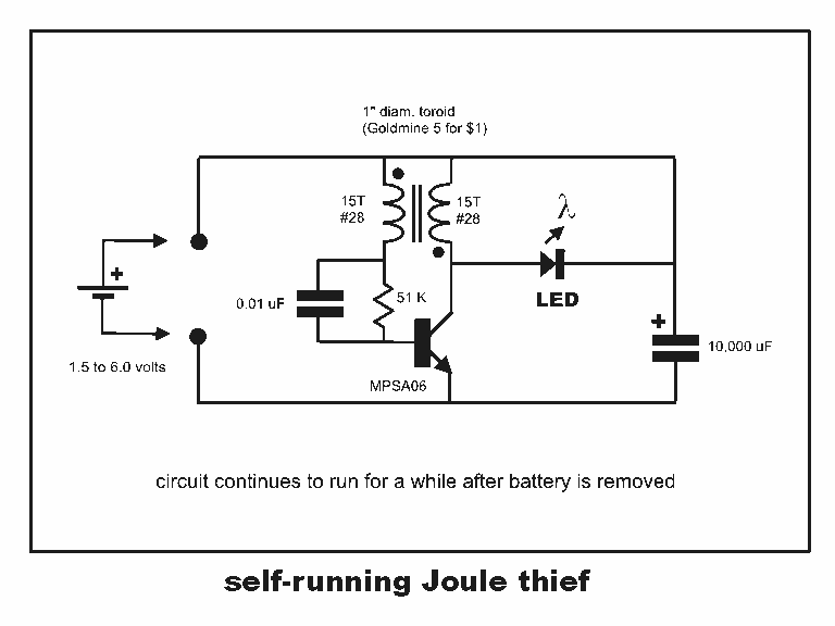
Professor Steven E. Jones' circuit demonstrates an 8x overunity. The concept of overunity refers to a system that produces more energy than is consumed, effectively achieving a coefficient of performance greater than one. In the context of Professor Steven E....
The purpose of this circuit is to animate shop windows using a capacitive sensor positioned behind a postcard-like banner. The card is placed against the glass inside the shop window, allowing visitors to activate the relay by placing their...