
NE 555 & LM 567 Remote Control Circuit

The remote control circuit design is an essential application in wireless communication systems, providing a straightforward means to control devices remotely. The transmitter section, centered around the NE555 timer IC, is configured in astable mode to generate a continuous square wave signal. This signal's frequency can be adjusted by varying the resistor and capacitor values in the timing circuit, allowing for custom frequency generation based on application requirements.
The receiver section employs the LM567 tone decoder IC, which is adept at detecting specific frequencies and outputting a signal when the correct frequency is received. The tuning process is critical; the variable resistor R1 allows for precise adjustments to ensure that the receiver is correctly aligned with the transmitter's output frequency. This tuning process can be facilitated by using an oscilloscope to visualize the frequency output from the transmitter and confirming that the receiver responds appropriately.
In addition to the basic functionality, it is crucial to consider the frequency separation between different channels in multi-channel applications. The recommendation of a 5 kHz difference between channels ensures that the LM567 can effectively distinguish between signals without interference, allowing for reliable operation in environments with multiple remote controls. The design can be expanded by incorporating additional channels, each with unique frequency settings, thereby enhancing the remote control system's versatility and application range.
Overall, the remote control circuit is a practical implementation of analog electronics, showcasing the integration of timing circuits with frequency detection capabilities, which can be adapted for various applications, including consumer electronics, robotics, and automation systems.Remote control circuit consists of two parts, one is transmitter and the other is receiver. A simple diagram is schematic remote control. The transmitter circuit`s transmitter IC is controlled by NE555. Receiver circuit works by the signal emitted frequency which is emitted by that transmitter circuit. Transmitted signal frequency must be equal to the frequency decoder of the receiver circuit. The NE 555 generated frequency is same that receive frequency of IC LM 567. The resistor R1 is a receiver variable to facilitate the process of tuning. The system works well when the circuit is ready. The first step is tuning by way of the transmitter is turned on continuously, while the receiver R1 to set the value to be able to detect the signal transmitter. The second part is the receiver is controlled by LM 567. The following is a schematic drawing recipient. In the picture on top of each channel is designed with a different frequency. By considering the bandwidth of the frequency detection signal LM 567, inter-frequency channels should have a big enough difference, let`s try with a difference of 5 KHz.
🔗 External reference
Related Circuits

Enable the Gene to progressively lower the power applied to the heating element, allowing it to reduce heat instead of switching on and off. This minimizes the temperature gradient within the drum and the maximum temperatures that the beans...
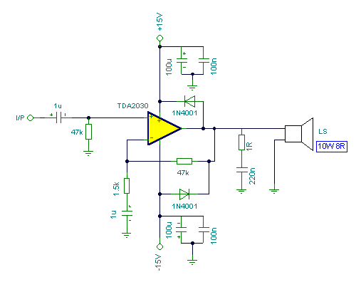
Connecting two TDA2030 through inexpensive power transistors allows for the creation of an amplifier capable of delivering higher power. This can be achieved by utilizing the component values specified in the schematic. To implement this circuit, two TDA2030 integrated circuits...

The TDA7294 is a monolithic integrated circuit housed in a Multiwatt15 package, designed to deliver high output power of up to 100W. It is intended for use as an audio Class AB amplifier in high-fidelity applications. The TDA7294 is a...
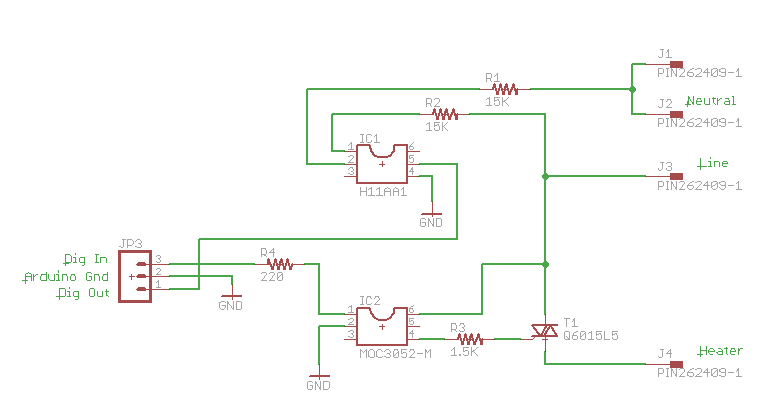
One method of controlling power to AC circuits utilizes a triac to switch the power on and off at precisely timed intervals synchronized with the AC signal. This technique is referred to as AC phase control and is commonly...
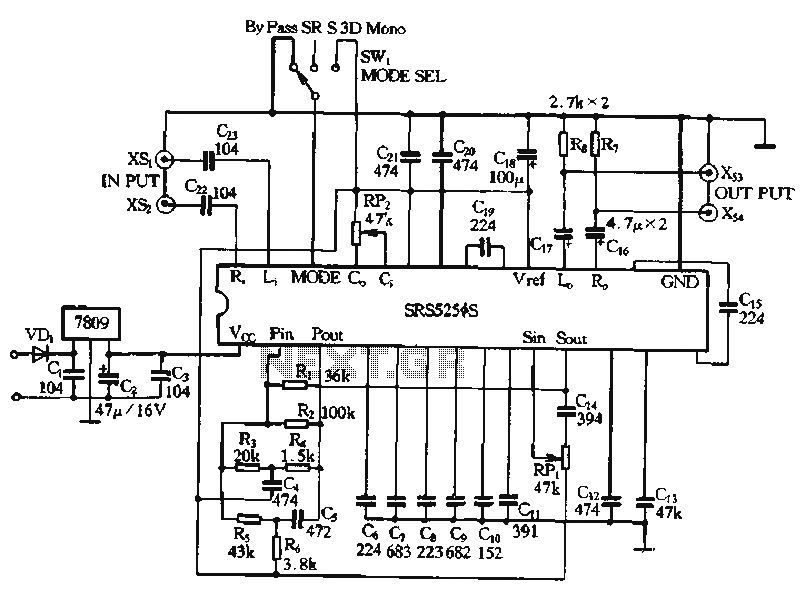
Typical application circuits for the Zheng brick SRS5250S are illustrated in the provided diagram. The SRS5250S features a pin diagram and a processing circuit that allows the user to switch between three operating modes: straight, SRS, and single-channel analog...
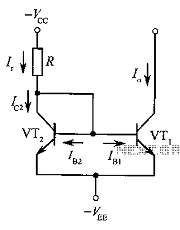
The circuit depicted is a mirror substantially constant current source circuit, in which transistors VT1 and VT2 are matched to each other. The figure illustrates that the current through Ir is equal to Ic2 plus the sum of base...