
NE 555 Electronic Metronome Electrical

The electronic metronome schematic typically consists of several key components that work together to produce a rhythmic sound at set intervals. The core of the metronome is usually a microcontroller or an integrated circuit (IC) that generates a clock signal. This clock signal determines the tempo, which can often be adjusted by the user.
In addition to the microcontroller, the schematic may include passive components such as resistors and capacitors, which are used to shape the waveform of the output signal. A piezoelectric speaker or a small audio transducer is commonly employed to produce the audible ticks or beats that signify the tempo.
Power supply considerations are also crucial in the design, with the circuit typically powered by batteries or a DC power supply. Voltage regulators may be included to ensure stable operation of the microcontroller and other components.
Furthermore, user interface elements such as buttons for tempo adjustment and LEDs for visual feedback may be integrated into the schematic. These components enhance the functionality of the metronome, allowing musicians to easily set their desired tempo and receive visual cues alongside auditory signals.
Overall, the electronic metronome schematic exemplifies a straightforward yet effective design that serves the fundamental purpose of providing a consistent tempo for practice and performance.Here is one example of the electronic metronome schematic. electronic metronome is very popular since it can be very simple, compact/small, .. 🔗 External reference
Related Circuits
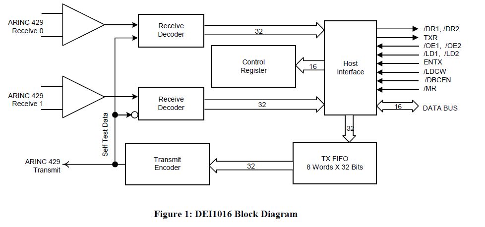
This document outlines the process of interfacing an Arduino with an ARINC 429 transceiver, illustrating the general methodology for connecting an Arduino to electronic circuits that can be applied to individual designs. The ARINC 429 bus is the predominant...
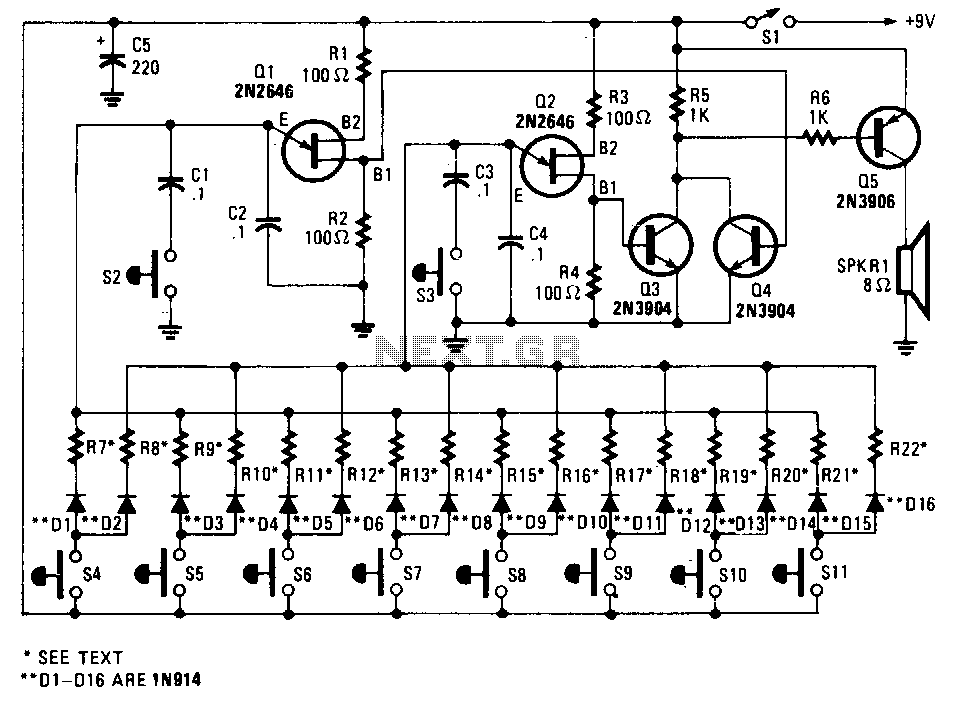
This circuit simulates the dual-tone drone sound produced by an unusual wind instrument. The urjunction transistors Q1 and Q2 are configured in similar audio-oscillator circuits. The frequency of each oscillator is determined by one of the two resistors selected...

This is a simple smoke alarm circuit using a timer IC, the NE555. The circuit operates by illuminating a Light Dependent Resistor (LDR) with a lamp. When smoke obscures the light from the lamp, the resistance of the LDR...
All of the components in this list are generally available through RadioShack for less than $20. It is highly recommended to use a breadboard for assembly, as mistakes are common for first-time builders, and soldering can complicate troubleshooting. This...
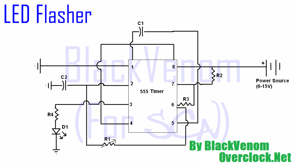
The circuit operates using an integrated circuit (IC) NE555 along with resistors R, RP, and capacitor C3, forming an astable multivibrator configuration. The output from pin 3 of the IC generates a square wave oscillation signal, which is passed...
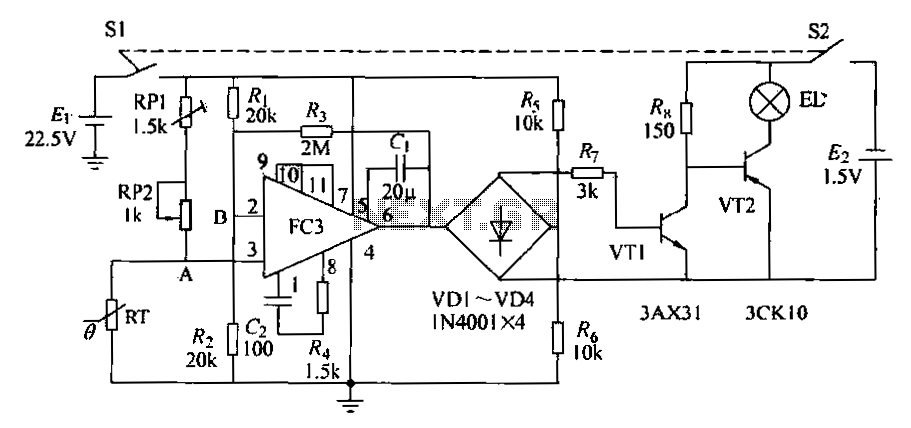
The circuit diagram illustrates an electronic thermometer. RT represents the thermistor, while A denotes an integrated operational amplifier. The diodes VD1 to VD4 provide a unidirectional output signal. The transistors VT1 and VT2 form a switching circuit. When the...