
ne602 vhf circuits

Radio-frequency (RF) schematics are essential for designing and implementing circuits that operate at high frequencies, typically ranging from 3 kHz to 300 GHz. The NE602 is a popular integrated circuit used in various RF applications, particularly in RF receivers. It functions as a double-balanced mixer, allowing for efficient frequency conversion, which is critical in RF communication systems.
RF receiver circuits are designed to capture and demodulate signals transmitted over the air. These circuits often include components such as antennas, amplifiers, mixers, filters, and demodulators. The design process begins with selecting an appropriate antenna that matches the frequency of interest, ensuring optimal signal capture.
Following the antenna, a low-noise amplifier (LNA) is typically employed to boost the weak incoming RF signals while minimizing added noise. The NE602 can then be utilized as a mixer to convert the RF signal to an intermediate frequency (IF) for easier processing. This is achieved by combining the RF signal with a local oscillator (LO) signal, which is also generated within the circuit. The choice of the IF frequency is crucial, as it affects the overall performance and selectivity of the receiver.
Subsequent stages in the RF receiver may include bandpass filters to eliminate unwanted signals and noise, ensuring that only the desired frequency range is processed. Finally, a demodulator is used to extract the information carried by the RF signal, which can be audio, video, or data.
In summary, RF receiver circuits encompass various components and design considerations that work together to effectively receive and process high-frequency signals. The NE602 plays a pivotal role in these designs, serving as a versatile mixer that facilitates efficient signal conversion and processing.Radio-frequency schematics (also see. ne602 datasheet and application note,.This page contain electronic circuits about Electronic RF receivers Circuits. This index has a wide collection of RF receivers, that can be.. 🔗 External reference
Related Circuits
These accessories are low-cost, high-speed, bifet-input operational amplifiers utilizing internally compensated voltage (BI-FET II technology). They require low supply voltages while offering a wide gain bandwidth product and fast slew rate. Additionally, well-matched high voltage JFET input devices accommodate...
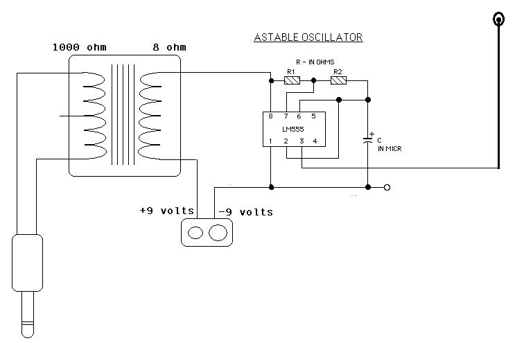
Two ICM7555 CMOS 555 timers are available, and there is an inquiry about effective AM radio transmitter circuits that utilize one or both of these timers. The ICM7555 is a low-power CMOS version of the classic 555 timer, which can...
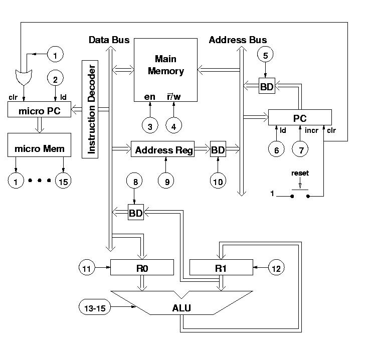
The diagram features a micro memory capable of storing up to 64 different addresses, each containing 15 bits, referred to as micro operations (MOPs). These MOPs govern all functions of the computer. Adjacent to the micro memory is the...
In the first circuit, the BC548 transistor is configured as a Colpitts oscillator, with the frequency being adjusted through the insertion of a crystal. A high-quality crystal will generate high-frequency oscillations, and the output at the collector is rectified...
This is a simple game show timer designed for beginners. The power source can be a standard 12-volt lantern battery or a battery pack made from C or D cells. The lamps used can be regular flashlight bulbs; the...

This game can be played individually or with friends. The circuit consists of a timer IC, two decade counters, and a display driver paired with a 7-segment display. The objective of the game is straightforward: the player who reaches...