
Circuit Diagram Of Slave Flash Light Control

The Slave Flash Light Control Circuit is designed to manage the operation of a secondary flash light in conjunction with a primary flash unit. This circuit typically operates on the principle of inductive coupling, where the 68mH inductor plays a crucial role in energy transfer and triggering the secondary flash light.
In this circuit, the primary flash light acts as the main source of illumination, which, when activated, induces a current in the 68mH inductor. This induced current serves to automatically trigger the secondary flash light, allowing it to illuminate shortly after the primary flash. The timing of the secondary flash can be adjusted by modifying the characteristics of the inductor and associated components, such as capacitors and resistors, which may be included in the circuit for timing control.
The design may also incorporate additional features such as a diode for rectification, ensuring that the current flows in the correct direction and protecting against potential back EMF generated by the inductor. A transistor may be used as a switch to control the activation of the secondary flash light based on the signal received from the inductor.
Overall, this Slave Flash Light Control Circuit provides a reliable method for synchronizing multiple flash lights, enhancing photographic applications or emergency lighting systems where additional illumination is required.The following circuit shows about Slave Flash Light Control Circuit Diagram. Features: 68mH Inductor, give auto trigger for secondary flash light, . 🔗 External reference
Related Circuits
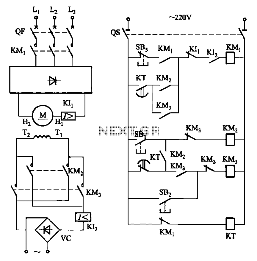
The circuit depicted in Figure 3-193 illustrates a separately excited DC motor. The brake circuit is not activated; therefore, positive reversals occur alternately using a delay action relay, ensuring that the motor reverses direction after coming to a stop. The...
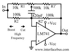
This discussion continues from the audio tone control topic, which introduced both passive and active tone controls. The follow-up topics may include a 2-Band Active Tone Control or a 3-Band Active Tone Control. An audio equalizer is utilized to...
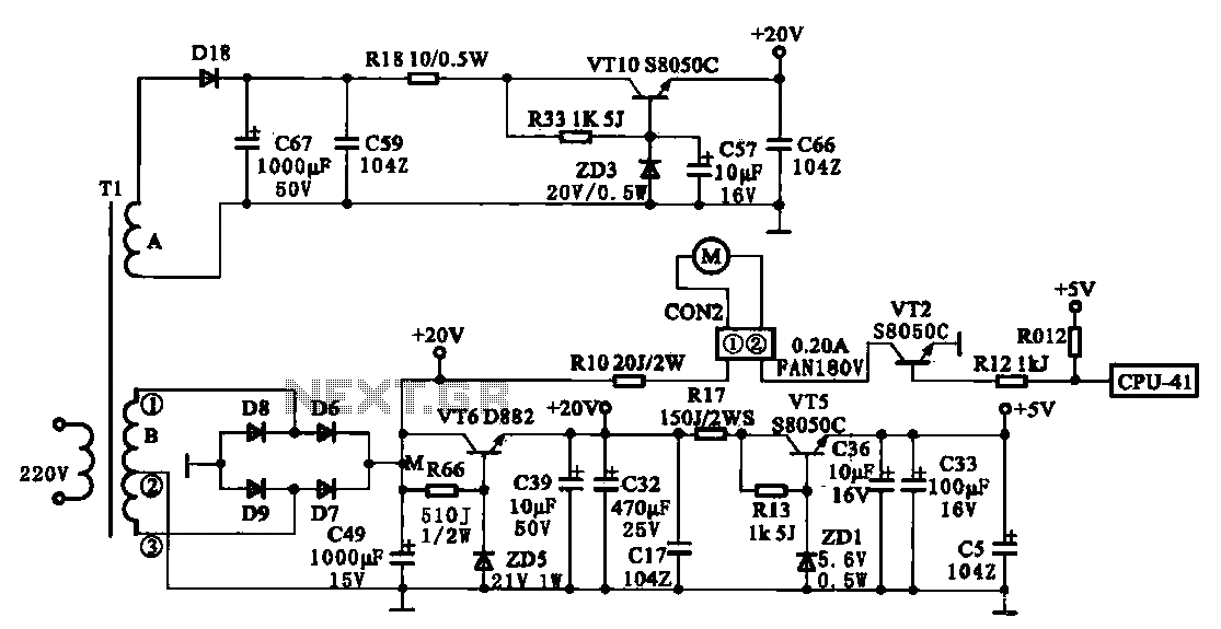
The JYC-22F type cooker low voltage power supply circuit is depicted. An AC 220 V power supply voltage is applied to a low-voltage transformer. The transformer has a primary winding (Tl) and two secondary windings (A and B), with...
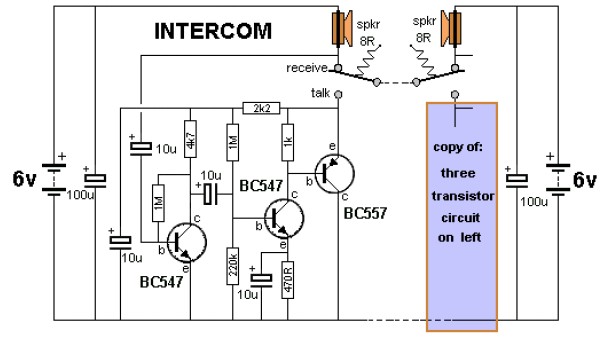
The key to avoiding instability (motor-boating) in a high-gain circuit is to power the speaker using a separate power supply. This circuit design allows for the connection of one or two additional stations. It is recommended to construct the...
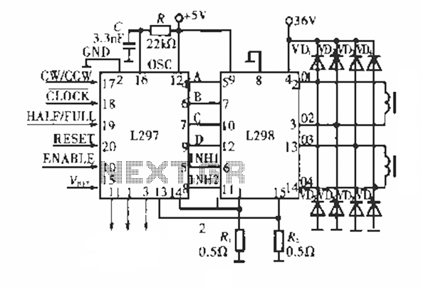
The circuit operates using a dedicated stepping motor controller, the L297. Pin 17 (CW/CCW) is utilized to control the rotation direction of the stepper motor. Pin 18 (CLOCK) regulates the speed of the stepper motor, while pin 19 (HALF/FULL)...
It is well known that pests like rats, mice, etc., are repelled by ultrasonic frequency in the range of 30 kHz to 50 kHz. Human beings can't hear these high-frequency sounds. Unfortunately, all pests do not react at the...