
Low Cost Burglar Alarm For Boats

The burglar alarm circuit is designed to provide an economical solution for security applications. It integrates a 12V power supply, which serves as the main energy source for both the strobe light and the reversing horn. The strobe light functions as the visual alert mechanism, flashing brightly to draw attention when the alarm is triggered. The truck reversing horn acts as the audible component, emitting a loud sound that serves to deter intruders and alert nearby individuals.
The core of the alarm system includes a motion sensor or a contact switch that detects unauthorized entry. When triggered, the sensor sends a signal to the control unit, activating the strobe light and the horn simultaneously. The circuit may also include a delay timer to prevent false alarms caused by pets or environmental factors.
In terms of construction, the circuit typically involves a relay that allows the low-power control signal from the sensor to switch the higher power loads of the strobe light and horn. The relay is essential for isolating the control circuit from the higher voltage components, ensuring safety and reliability.
For additional features, the circuit can be equipped with a reset switch that allows the user to deactivate the alarm after it has been triggered. This functionality is crucial for user convenience, especially in scenarios where the alarm may be activated accidentally.
Overall, this burglar alarm system is an effective and cost-efficient solution for enhancing security in residential or commercial settings, utilizing straightforward components to deliver reliable performance.This low-cost burglar alarm employs a 12V strobe light and a truck reversing horn as the visible and audible alarm outputs while the alarm itself is a 12V.. 🔗 External reference
Related Circuits

This is a collection of compact, self-sufficient alarm circuits designed for low standby current, making them ideal for battery operation. Some circuits are activated by normally-open and normally-closed switches, while others respond to variations in light or temperature. This...

This circuit is designed to power a laptop computer using a solar power setup. The computer requires 12V at 3.3A. The circuit employs a linear regulator with a MOSFET (Q4) as the series pass device. A 100kΩ resistor provides...

This is a low distortion crystal oscillator circuit. This circuit generates a sine wave that has low phase noise and distortion. This circuit can be used for various applications. The low distortion crystal oscillator circuit is designed to produce a...
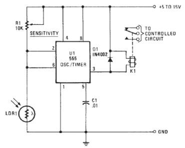
The following circuit illustrates a Photo Alarm Electronic Circuit. This circuit is based on the 555 Timer IC and incorporates features such as an LDR (light-dependent resistor). The Photo Alarm Electronic Circuit utilizes a 555 Timer IC configured in monostable...

The amplifier utilizes a grounded grid circuit featuring either the Eimac 3CX1000A7 or 8877 ceramic/metal triodes designed for linear operation within the HF and VHF frequency ranges. It delivers a legal power output of 1500 watts PEP and continuous...

This line-following robot sensor, or surface scanner for robots, is a compact, stamp-sized infrared proximity detector designed for short-range detection, operating within a range of 5 to 10 mm. The line-following robot sensor operates using infrared light to detect the...