
Negative Voltage Hot Swap Controllers in SOT-23

The LTC4251 series of Hot Swap controllers is engineered for applications requiring the safe operation of electronic boards in live environments, particularly in telecommunications systems. These controllers are critical for protecting sensitive components from damage due to voltage fluctuations during insertion or removal.
The three-stage current limiting mechanism is a key feature of the LTC4251 controllers. The timed circuit breaker provides an initial layer of protection by disconnecting the load after a predetermined time if an overcurrent condition persists. This is complemented by active current limiting, which continuously monitors the output current and adjusts it to prevent damage to the board. The fast feed-forward path is particularly important during transient events, as it allows the controller to react quickly to sudden increases in current, thereby limiting peak currents that could cause catastrophic failures.
The programmable undervoltage and overvoltage detectors further enhance the reliability of these controllers. They ensure that the load is disconnected when the input supply voltage falls below or exceeds the designated thresholds, thus safeguarding the entire system. The shunt regulation feature allows the LTC4251 controllers to operate safely even with input voltages significantly higher than the typical operating range, making them versatile for various applications.
The multifunction timer integrated into the LTC4251 series is essential for managing the start-up sequence and ensuring that the circuit breaker operates effectively. By delaying the initial start-up, the timer allows for stabilization of the input voltage before the load is connected, minimizing the risk of damage due to inrush currents.
In summary, the LTC4251, LTC4251-1, and LTC4251-2 Hot Swap controllers provide robust solutions for managing negative voltage applications in live environments, with advanced features for current limiting, voltage monitoring, and safe operation. Their design is particularly well-suited for telecom applications, where reliability and safety are paramount.The LTC4251/LTC4251-1/LTC4251-2 negative voltage Hot Swap controllers allow a board to be safely inserted and removed from a live backplane. Output current is controlled by three stages of current limiting: a timed circuit breaker, active current limiting and a fast feed forward path that limits peak current under worst-case catastrophic fault con
ditions. Programmable undervoltage and overvoltage detectors disconnect the load whenever the input supply exceeds the desired operating range. The supply input is shunt regulated, allowing safe operation with very high supply voltages. A multifunction timer delays initial start-up and controls the circuit breaker`s response time. The LTC4251 UV/OV thresholds are designed to match the standard telecom operating range of 43V to 75V.
The LTC4251-1 UV/OV thresholds extend the operating range to encompass 36V to 72V. The LTC4251-2 implements a UV threshold of 43V only. 🔗 External reference
Related Circuits
When the input voltage is 0 the LED glows. The LED stops glowing when the voltage rises to the level determined by R2. Reverse + and - pins to reverse operating mode. To set voltage at which LED goes...
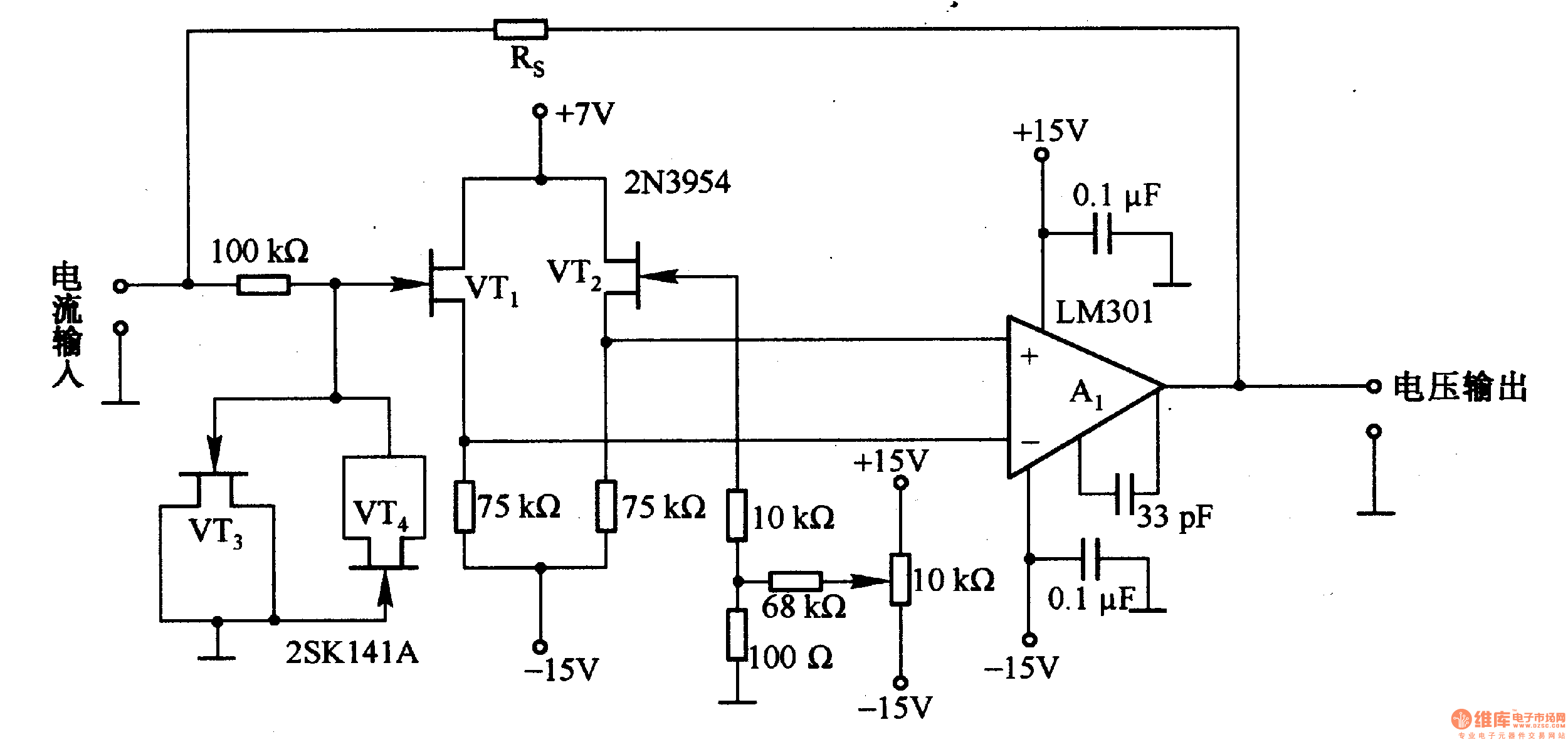
This is a low-input impedance conversion circuit with the reference resistor RS connected to the amplifier's feedback loop, resulting in an input impedance close to zero. The input current flows into the output end of the operational amplifier (Op-Amp)...
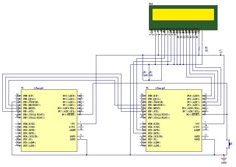
SPI stands for Serial Peripheral Interface, which is the simplest among all communication protocols. Eight-bit data registers in the devices are connected by wires. These data registers function as shift registers, with one device controlling the data exchange within...

A simple linear voltage-controlled amplifier can be constructed with one operational amplifier (op amp) and two junction field-effect transistors (JFETs). This amplifier can achieve an 80-dB dynamic control range with less than ±0.2% linearity error for 0 V. The described...
Author Mazi Hosseini describes a simple, low-cost voltage-controlled current source using two operational amplifiers that provides a good range of current and maximum load. The circuit described by Mazi Hosseini utilizes two operational amplifiers (op-amps) to create a voltage-controlled current...
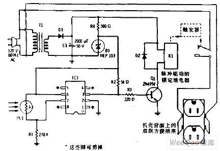
The flash beam can be utilized to power remote control devices for AC power applications. A key feature of this device is its memory function, which allows it to supply power continuously. Upon the second activation, the power will...