
Negative Voltage Load Swtich

The good thing about this design is that I can make use of the system I/O voltage to control the on/off and this is the whole idea. However, there are many types of load switches that turn off negative voltages. Here is the suggestion,
A circuit that controls negative voltage loads can be implemented using a load switch designed specifically for this purpose. The primary function of this circuit is to manage the power delivery to loads that require a negative supply voltage, such as bias voltages for LCD panels, RF amplifiers, and audio amplifiers.
In this design, a load switch IC capable of handling negative voltages is utilized. The load switch will typically have an input pin connected to the system's I/O voltage, which acts as the control signal. When the I/O voltage is high, the load switch allows the negative voltage to pass through to the load, thus powering it on. Conversely, when the I/O voltage is low, the load switch disconnects the negative voltage from the load, effectively turning it off.
The load switch IC should be selected based on several parameters, including the maximum current rating, the voltage drop across the switch (on-resistance), and the maximum negative voltage it can handle. Additionally, it is important to consider the switching speed, which can affect the performance of sensitive applications such as RF amplifiers.
To ensure stable operation, bypass capacitors should be placed close to the load switch, particularly on the input and output sides. This helps to filter out any noise and provides a stable voltage supply during switching events.
For applications requiring precise control, a microcontroller can be employed to manage the I/O voltage signal, allowing for programmable control of the load switch. This adds flexibility to the design, enabling the system to turn off the negative voltage load under specific conditions, such as when the device enters a low-power state or when certain operational thresholds are met.
In summary, the proposed circuit efficiently manages negative voltage loads using a dedicated load switch controlled by the system's I/O voltage, providing a reliable solution for applications such as LCD biasing, RF amplification, and audio signal processing.The idea is simply to turn off the negative voltage load. Some examples:- - Bias votlages for LCD panels - RF Amplifiers - Audio Amplifiers The good thing about this design is that i can make use of the system i/o voltage to control the on/off and this is the whole idea. However, there are many many type of load switches that turn of negative voltages. Here is the suggestion, 🔗 External reference
Related Circuits
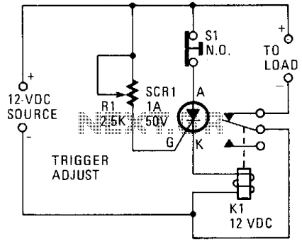
A silicon-controlled rectifier (SCR) is connected in parallel with the 12-V line and linked to a normally-closed 12-V relay, designated as K1. The gate circuit of the SCR is utilized to monitor the applied voltage. While the applied voltage...
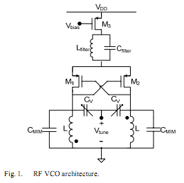
The oscillator is designed to tune from 1.8 GHz to 2 GHz for typical cellular telephony applications. An extended tuning range can be obtained by adjusting the ratio between the varactor capacitance and fixed capacitance in the tank. PMOSFETs...
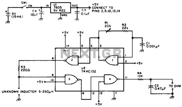
The adjustable voltage monitor can be used to check whether the voltage in a circuit remains within a given range. If the DC voltage is less than the voltage at pin 5 of U1-B, then LED1 will light. If...
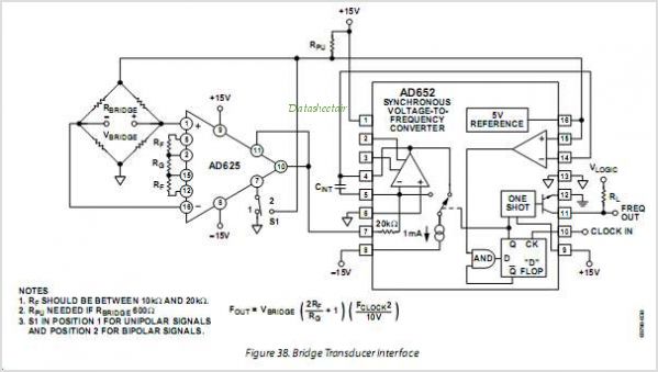
The AD654 is a monolithic voltage-to-frequency (V/F) converter that comprises an input amplifier, a precision oscillator system, and a high-current output stage. A single resistor-capacitor (RC) network is all that is needed to configure any full-scale (FS) frequency up...
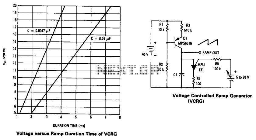
The current source created by Q1 in combination with capacitor C1 determines the duration of the ramp. As the positive DC voltage at the gate varies, the peak point firing voltage of the Programmable Unidirectional Thyristor (PUT) is altered,...
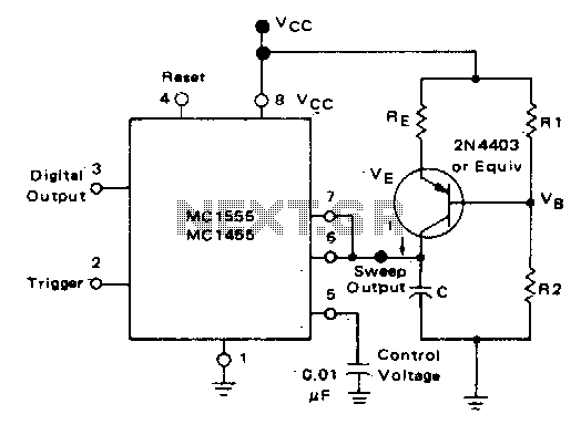
In the monostable mode, the resistor can be replaced by a constant current source to provide a linear ramp voltage. The capacitor still charges from 0 to 2/3 Vcc. In a monostable multivibrator configuration, the circuit typically consists of a...