
Neon Desklamp

The circuit designed for powering a 6-inch, 4-watt fluorescent tube from a 12-volt supply consists of several key components to ensure efficient operation and reliable performance. The primary components include a transformer or inverter, a ballast, and the fluorescent tube itself.
The circuit begins with a 12-volt DC supply, which may come from a battery or an AC to DC converter. The voltage needs to be converted to a higher AC voltage suitable for the fluorescent tube. This can be achieved using a small inverter circuit that steps up the voltage. The inverter typically consists of a switching device such as a transistor or MOSFET, which alternates the current flow to create an AC output.
Next, a ballast is required to regulate the current flowing through the fluorescent tube. The ballast limits the current to prevent the tube from drawing excessive power, which could lead to overheating and failure. In this case, an electronic ballast may be used for better efficiency and to provide a more stable operation compared to traditional magnetic ballasts.
The fluorescent tube operates by ionizing the gas inside the tube, which emits ultraviolet light when an electric current passes through it. This ultraviolet light then excites a phosphor coating on the inside of the tube, producing visible light. The specifications of the tube indicate that it operates at 4 watts and requires a current of 300 mA. Therefore, the ballast must be designed to maintain this current level while accommodating the tube's electrical characteristics.
In summary, the circuit consists of a 12-volt DC supply, an inverter to step up the voltage, an electronic ballast to regulate current, and the fluorescent tube itself. Proper design considerations must be taken into account to ensure efficient operation, including component ratings, thermal management, and circuit protection features. This setup provides a practical solution for illuminating spaces with a compact fluorescent tube while utilizing a common 12-volt power source.This circuit will power a 6 inch 4 Watt fluorescent tube off a 12 volt supply, consuming 300 mA. 🔗 External reference
Related Circuits
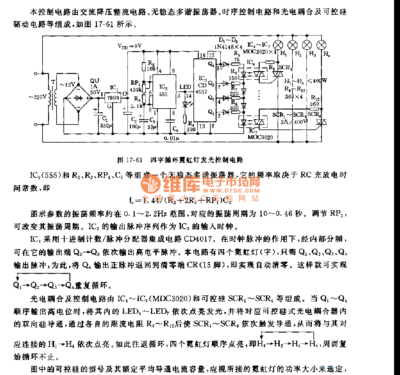
This control circuit consists of an AC step-down rectifier circuit, an astable multivibrator, a timing control circuit, an optocoupler circuit, and an SCR driving circuit, as illustrated in Figure 17-61. The astable multivibrator is formed using IC2 (555), resistors...

This circuit is similar to the LED clock using 12 neon indicator lamps instead of LEDs. It operates from 2 high capacity ni-cad cells (2.5 volts) which keep it going for a couple weeks. High voltage (70 volts) for...
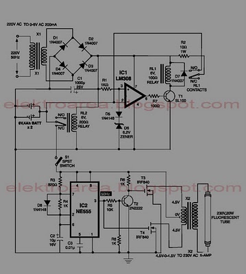
This circuit is an IC-controlled emergency light system. It automatically switches on the light during a mains failure and includes a battery charger with overcharge protection. When the mains power is absent, relay RL2 is in a de-energized state,...
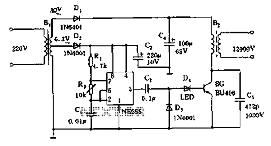
The neon voltage power supply circuit is straightforward to construct, offering stable output power and other desirable characteristics. The core component of this circuit is the NE555 timer, which generates a high-frequency oscillation signal in the range of 15...
In this circuit, one, two or three neon indicator bulbs can be made to flash in sequence at rates determined by the R and C values. In the single stage circuit, using one lamp, the capacitor charges through the...
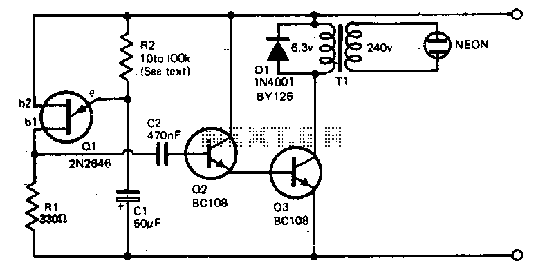
The voltage required to ignite the neon tube is generated by utilizing a standard filament transformer (240-6 V) in reverse. The battery drain is minimal, approximately 1 to 2 milliamps for a nine-volt battery. The pulses from Q1, a...