
Newb question on 12AU7 gain stage

The gain stage circuit designed using Decware's Zkit4 is intended to provide impedance matching and signal buffering for the LM3875 gain clone amplifier. This configuration is beneficial as it isolates the input source from the load, ensuring that the signal integrity is maintained while driving the power amplifier.
The Zkit4 typically consists of a simple transistor-based amplifier configuration, which may include components such as resistors, capacitors, and transistors arranged to provide the desired gain characteristics. The output of this gain stage can be connected directly to the input of the LM3875, which is a high-performance audio power amplifier capable of delivering substantial output power with low distortion.
In this setup, the gain stage will enhance the input signal, allowing the LM3875 to operate effectively without being affected by the source impedance. The design of the gain stage should consider factors such as bandwidth, gain, and noise performance to ensure that the overall audio quality is preserved. Additionally, proper power supply decoupling and grounding techniques should be employed to minimize any potential interference and maintain a clean signal path.
To implement this system, it is essential to select appropriate component values for the gain stage to achieve the desired gain and frequency response. The circuit layout should also be optimized for minimal signal degradation, which may involve careful routing of traces, especially in high-frequency applications. By following these guidelines, the gain stage will effectively function as a buffer, enhancing the performance of the LM3875 gain clone amplifier.Hello Bottleheads, I am building this gain stage from Decware`s Zkit4 to use as a buffer in front of an LM3875 gain clone. The chip amp has plenty of.. 🔗 External reference
Related Circuits
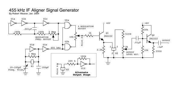
The resonator appears to be highly susceptible to harmonics. For instance, if the resonator frequency is set at 455 kHz, it also permits frequencies at 910 Hz, 1820 kHz, and 3.640 MHz, which seems to be dominant. Frequencies around...
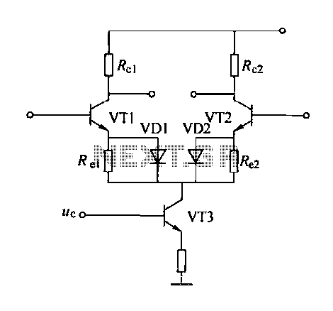
A controllable gain amplifier functions as an automatic gain control circuit within the execution unit. The primary methods for controlling the amplifier's gain involve two approaches: one is by adjusting certain parameters of the amplifier itself, such as emitter...
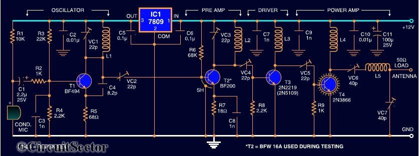
Here is the circuit diagram of a four RF stage FM transmitter. The stages include a very high frequency (VHF) oscillator built around the HF transistor BF494, a pre-amplifier using the BF200 transistor, a driver transistor 2N2219, and a...
The feedback in this circuit is DC coupled, connecting directly from the plate of the second triode to the cathode of the first triode, as opposed to the earlier design which utilized AC coupled feedback. The previous version exhibited...
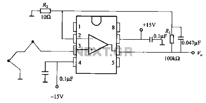
The OP07 is a low drift operational amplifier with a maximum voltage drift of 30 µV/°C and a maximum drift of 0.6 mV/V/°C. It features low noise characteristics with a maximum noise level of 0.6 pV/√Hz, offering ultra-stability with...
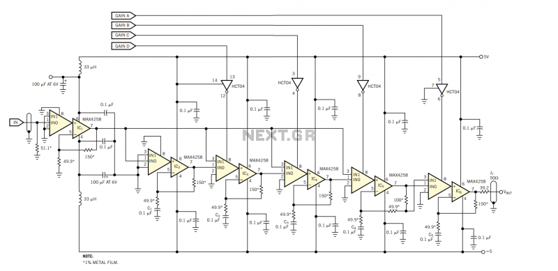
The amplifier in Figure 1 originally served as the photomultiplier preamplifier in a Doppler system intended for eventual operation in the Martian atmosphere. The design is based on a switchable array of six Maxim MAX4258 dual-channel video multiplexer-amplifiers, IC1...