
Inverse Voltage Controlled Voltage Source

The described circuit is a voltage servo system designed to provide precise control of output voltage based on a smaller input control voltage. The configuration allows for flexibility in power supply requirements, enabling operation across a wide range of output voltages. The operational amplifiers are critical components in achieving the desired performance, with U1A, U1B, and U1C serving distinct roles in the feedback and control mechanisms.
U1A's function as a linearizing element is essential for maintaining output stability, particularly as the output approaches its lower limits. The negative gain provided by U1A ensures that the control loop can effectively manage variations in output voltage, compensating for any non-linear behavior that may arise near the lower voltage threshold.
Op-amp U1B, with its gain of -1, serves to invert the control signal, allowing for the inverse relationship between the control voltage and output voltage. The introduction of an offset voltage of 2Voff helps to calibrate the output, ensuring that it meets specific application requirements.
The unity buffer configuration of U1C is vital for decoupling the control loop from the load, allowing the circuit to respond to changes in control voltage without being adversely affected by load variations.
The choice of resistors R3 and R5 is crucial as they not only draw current but also affect the overall accuracy of the output voltage. Careful selection of these components can minimize output errors, thereby enhancing the performance of the circuit.
In summary, this voltage servo circuit is designed for applications requiring precise control over output voltage, with a focus on maintaining linearity and stability across a broad range of operating conditions. Proper component selection and configuration are key to achieving the desired performance characteristics.This circuit allows a smaller control voltage to inversely linearly control a larger output voltage Vo. Another feature is that Vsp the supply to the op-amps can be lower than the output voltage so in theory this circuit could control a output voltage of any magnitude, since the op-amps use a different supply.
This will work with single supply op- amps provided that Vsp>VCmax - Vrail, and Vsn<- Vrail, where Vrail is the dead zone of the upper rail, this is typically. 5V to 1V. This circuit will lose linearity as it attempts to drive the output voltage to zero, unless the dead zone around the rail is zero, because the control voltage approaches VS as Vo goes to zero. This non-linearity will be manifest as a rapid jump of Vo to zero, as Vc increases linearly. Some op-amps have nearly rail to rail input capability, so VS depends on the op-amp you want to use. Since as Vo goes to zero, the input to the op-amp 1C must be able to work near 0V, which can be accomplished by proper selection of a single supply op-amp, or by using a negative supply rather than ground.
R3 and R5 draw current and present a small output error on the output voltage. The op-amp U1C is a unity buffer, which is needed to isolate the load from the control loop. Op-amp U1B provides gain of -1 and provides and offset voltage of 2Voff. Op-amp U1A linearizes the transistor through its large negative gain. Do you need help with an electronics design Daycounter provides contract electronics design services. Contact us to give you a quote on your electronics design project. Warning: include() [ function. include ]: URL file-access is disabled in the server configuration in /usr/local/apache2/htdocs/daycounter/Circuits/Voltage-Servo-Inverse/Voltage-Servo-Inverse.
phtml on line 171 Warning: include( [ function. include ]: failed to open stream: no suitable wrapper could be found in /usr/local/apache2/htdocs/daycounter/Circuits/Voltage-Servo-Inverse/Voltage-Servo-Inverse. phtml on line 171 Warning: include() [ function. include ]: Failed opening ` for inclusion (include_path=`. :/usr/local/php5/lib/php`) in /usr/local/apache2/htdocs/daycounter/Circuits/Voltage-Servo-Inverse/Voltage-Servo-Inverse.
phtml on line 171 Warning: include() [ function. include ]: URL file-access is disabled in the server configuration in /usr/local/apache2/htdocs/daycounter/Circuits/Voltage-Servo-Inverse/Voltage-Servo-Inverse. phtml on line 177 Warning: include( [ function. include ]: failed to open stream: no suitable wrapper could be found in /usr/local/apache2/htdocs/daycounter/Circuits/Voltage-Servo-Inverse/Voltage-Servo-Inverse.
phtml on line 177 Warning: include() [ function. include ]: Failed opening ` for inclusion (include_path=`. :/usr/local/php5/lib/php`) in /usr/local/apache2/htdocs/daycounter/Circuits/Voltage-Servo-Inverse/Voltage-Servo-Inverse. phtml on line 177 🔗 External reference
Related Circuits
This simple circuit is a good solution to the powering a dual supply op amp from a single battery problem. The circuit simply takes a positive voltage and inverts it. It uses only one 555 timer and a few...
An exhaust fan is a crucial component in kitchens. This document presents a simple circuit designed to control kitchen fans by monitoring the ambient temperature. It is built around... The circuit for controlling an exhaust fan based on ambient temperature...
The hobby circuit described utilizes a unique method to generate approximately 12,000 volts with a current of about 5 microamperes. It employs two silicon-controlled rectifiers (SCRs) that form two pulse generator circuits. These SCRs discharge a 0.047 microfarad, 400-volt...
This circuit diagram is provided for those interested. It is a small circuit that takes an input of 1.5 volts and outputs 120 volts. The circuit in question is a voltage step-up converter, commonly referred to as a boost converter....
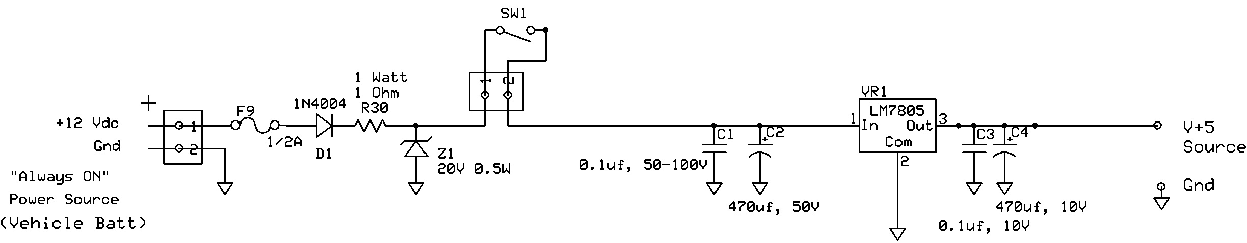
The circuit regulates approximately 12V from the car battery down to 5V for use by an Atmel AVR microcontroller. The presence of two capacitors on each side of the linear regulator LM7805 raises questions regarding their purpose. It is...
It cannot be 0 volts, as the current does not flow freely due to the presence of the resistor. This results in one side being more negatively charged and the other side more positively charged, as electrons can move...